We always used product of the means = product of the extremes using a perpendicular bisector, (diameter of circle), to calculate radius depth. Used the sine of head cant formula all of the time with no problems working on aircraft.It appears that you are expecting the arc to intersect a true radius at 3 points (both ends of chord and center of arc). I believe it would have to be a true radius for that to occur. When I used it, I cut to width and depth was whatever it was.
-
Welcome back Guest! Did you know you can mentor other members here at H-M? If not, please check out our Relaunch of Hobby Machinist Mentoring Program!
You are using an out of date browser. It may not display this or other websites correctly.
You should upgrade or use an alternative browser.
You should upgrade or use an alternative browser.
Cutting a simulated curved groove. Confirmation of formula for head tilt angle.
- Thread starter Parlo
- Start date
- Joined
- Feb 21, 2022
- Messages
- 786
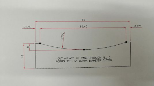
I also found this dimension for the two end points.We always used product of the means = product of the extremes using a perpendicular bisector, (diameter of circle), to calculate radius depth. Used the sine of head cant formula all of the time with no problems working on aircraft.
I then transposed this chord to the 80mm cutter diameter.
This gave a dimension perpendicular from the centre of the chord to the perimeter of 15mm.
I assumed that at 15mm from the cutter perimeter would cut this chord length.
So I used 15mm as my hypotenuse and the depth of groove - 5mm as the opposite side to the tilt angle.
Sin angle = 5/15 gives 19.47 degrees.
- Joined
- Feb 21, 2022
- Messages
- 786
Thanks Martin.My figure comes up as 15.5 degrees. Words of warning, the kid in the meme was me when I was nine.Lol
Martin. View attachment 451509
My figure was 19.47 degrees
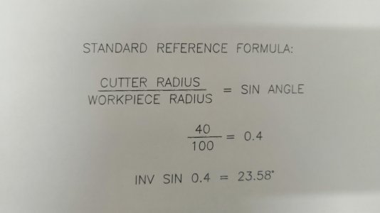
The standard formula gives 23.58 degrees.
I used a Huron mill way back with a unversal head & there were lots of tables in the manual for tilting the head. There were angles to give certain radii with common cutter sizes. I don't remember any references to the depths though.
Setting the head at an angle will cut different approximations at different depths. To clarify further - the ratio of the chord length to the depth would change at different depths. It seems to me that there can't be a specific angle for a specific radius without any reference to the depth in the calculations.
I'll try my figure first today and re-cut using yours if it does not give the chord/depth ratio I am looking for. - 62.45:5
- Joined
- Feb 21, 2022
- Messages
- 786
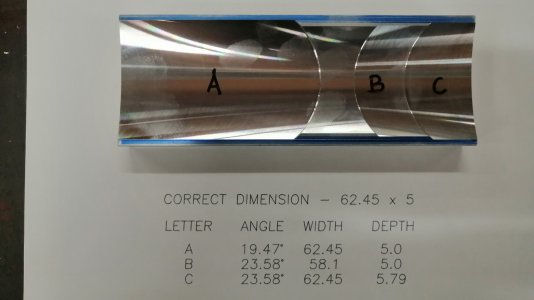
I cut the groove to the drawing with the correct width and depth at my calculated 19.47 degrees and it worked fine.
I also cut using the standard formula which gave 23.58 degrees.
At the correct depth the width was 4.4mm too narrow.
At the correct width the depth was 0.79 too deep.
In conclusion there does not seem to be a common tilt angle to cover a particular radius / cutter combination. The depth needs to considered to get the curve to pass through all 3 points. Using the common formula - cutter radius divided by the required radius = sin of the head tilt angle does not work well and is a poor approximation.
There is a method to calculate the curve that will pass through the 2 endpoints and the midpoint of any segment of a radius. I haven't refined it yet, but I will post the method.
There is a short video below showing the 3 tooth face mill cutting the groove.


Attachments
- Joined
- Apr 23, 2018
- Messages
- 6,617
I'm glad you worked it out to an acceptable result. As we figured out, the arc isn't an arc because the radius isn't constant. A curve fitted to three points is better approximated here as a bezier curve that can take many forms while still passing through all three points, than as a segment of a circle. Conical math would be the most correct representation, though.
IMHO, There are few instances where an exact radius is required. In most of the applications that I have used generated radii, it was used to reduce stress. We had a 39” radius that we had to machine on a J-79 engine exhaust flange. Had a radius gauge provided with the job to verify the radius. Did it on a K & T #2 with a universal head and a rotary table, and a large flycutter. The senior machinist on the job and our engineering department had approved the process. My .02There is a method to calculate the curve that will pass through the 2 endpoints and the midpoint of any segment of a radius. I haven't refined it yet, but I will post the method.
- Joined
- Feb 21, 2022
- Messages
- 786
I think it is an ellipse. If I draw a cylinder the same diameter as the cutter and tilt it, the end face becomes an ellipse when viewed along the direction of cut. This is the path the tool insert follows relative to the part when cutting & therefore the shape it leaves on the workpiece.I'm glad you worked it out to an acceptable result. As we figured out, the arc isn't an arc because the radius isn't constant. A curve fitted to three points is better approximated here as a bezier curve that can take many forms while still passing through all three points, than as a segment of a circle. Conical math would be the most correct representation, though.


