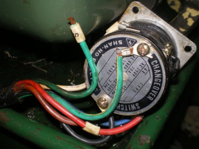
craftex cx701 wiring super issues. HELP PLEASE

bluecollarcult

Registered
Registered
Joined
Dec 5, 2012
Messages
9
ok, first post on this site. Long story short i bought a craftex cx701 from busy bee tools. I paid half price for the lathe because the hood over the electrical had been damaged. just a small ding. when i talked to the guy at busy bee he told me warranty, return etc. was the same as any other sale. I was also told the lathe worked like new. When i recieved the machine i seen right away that the fuse was blown, so i replaced that and still no power, keeps tripping my shop breaker and blowing fuses. Now busy bee is saying no warranty, no nothing because it was a "salvage sale". Funny they never told me that until after i pay for it and when i tell them about the problems. Also im six hours away from the closest store, if i was closer this situation would be diffrent, believe me. So now im taking apart the machine looking at the wiring and i see that the wiring schematic in the manual, the one on the machine itself and the actaul wiring in the machine are all contradicting each other. I'm no electrician but i think i have it narrowed down to the speed control board, but i really need to know what the wiring on a running machine looks like. Someone has been in this machine before and things are not as they should be, and the wiring schematics just dont line up, period. Is there anyone out there who could give me a hand? photos, homemade wiring schematics, talk me through it? I build custom motorcycles ( old stuff, not OCC!), and this is really slowing me up. Ive spent three shop days working on this thing. Id do my best to make it worth your while. I see that precision mathews sells the same 11 x 27, my advice would to be to buy from them not busy bee if you have the choice. Even though i didnt buy from them the guy at precision mathews was 100x the help anyone at busy bee was, and they have parts in stock. busy bee told me 3-6 months for replacement parts. thanks all, i really do appreciate it.​
 
At the risk of sounding trite often a damaged machines electrical problem is "damage". 1st thing I'd do is LOOK. Look really hard for shorted/nicked wires. Wires pulled from crimped on eyes can be hard to find if they flip around behind something when they get loose.

7switch.JPG

While making mechanical repairs to my 12x36 this starter field wire came loose and was hidden behind the switch, causing the lathe not to run.

Also remember a schematic simply shoes the connections and certainly not the wires actually routing. In the schematic a wire may appear very long but really be 1" long or vice versa.

I'm thinking your problem is probably (hopefully) as simple as above. Usually a bad board won't trip breakers without scorching or getting obvious damage.

Steve

7switch.JPG
 
thanks. No no loose wiring, ive gone over every connection more times then i can count, and any that where questionable i re crimped myself. The people i have talked to said that when there is an issue, it is usually the speed control board. I disconected power to there and no breakers tripping, after testing im thinking it is in the bridge rectifiers. The issue with the schematics isnt an issue of scale or orientation but in the simple fact that the number of connections, terminals etc. just doesnt match up. For example - - on both schematics it shows three lines comin into the filter hot nuetral ground. with four terminals being available on that side. In the machine itself there is four lines coming in ( one of which is unlabeled, and not on the schematic, but has factory connections) and five available terminals. But no where does it show two wires joining the same terminal. It really is tough to explain. The whole machine is like that. The available schematics are kinda what i can gather as a " ballpark, do it something along these lines" universal chinese drawing. thanks
 
The rectifier is one place where you can trip breakers with out frying a board. A bridge rectifier is simply 4 diodes and pretty easy to test with an ohm meter.

Maybe some pictures and link to the schematic could help.

The point I was trying to make is that the schematic may show a a connection at any point of a conductor. IE a connection to a motor wire may appear to be on the controller board while the connection is made in the motor box itself. You understand that I see, but it has bedeviled many people. A wiring diagram would show the connections and locations so in the example above the connection would be shown at the motor itself.

Steve
 
here it is from page 26
 

Attachments

  • CX701 wiring.pdf
    77 KB · Views: 15
Back
Top