Converter (?) help needed

Would benefit from some filtering also, so if you can find some (2) large electrolytic capacitors, add them to the circuit. Google will turn up millions of hits on a basic bridge rectifier circuit.
 
Bill,
If you don't need rpm adjust-ability, go to Radio Shack and get a full wave bridge. ($1.39-$2.69) It will convert AC to DC. Be sure to get one rated for more current then your motor. Connect the AC to "AC" and your motor to "DC" on the bridge.

Knowing full well that there is going to be a debate over my answer, I'll start with these comments. There will be a short time when the voltage output of the bridge will be in excess of 115V. There will also be a time when it's less. It happens so fast, the motor won't care. The average will be 115V. The LOAD will control the current draw, which determines the heat generated. If you are nervous, keep checking the motor for excess heat for a while.

Dave J.

Would benefit from some filtering also, so if you can find some (2) large electrolytic capacitors, add them to the circuit. Google will turn up millions of hits on a basic bridge rectifier circuit.

Similar situation for me. Got a treadmill motor 1 HP 6950 rpm@ 120 VDC and I think (since I'm away from it right now) continuous duty 9 amps at 75 VDC. I think it has 5 leads and though I wish now I'd noticed it was DC when I got it at the scrap yard, I didn't get the controller since I assumed( everyone knows what that means)it was AC and the controller was only for speed control. I liked the 6950 RPM and hoped to make a tool post grinder with it.A bridge rectifier is one thing to look at and another to know how to wire it and then there is the 5 motor leads and possibly throwing in some capacitors. Since I am unfamiliar with the component parts, how about a wiring clue or diagram for "Dummies". I was planning on speed control with pulleys at the grinding wheel.
 
Similar situation for me. Got a treadmill motor 1 HP 6950 rpm@ 120 VDC and I think ...
I really don't want to try that treadmill out!! Sure it isn't some much slower RPM? Of course it might be a CNC Treadmill.

Chris
 
Just guessing a little here, but I'm thinking 4 leads from the motor. Should have a red and a black for the power and a couple of smaller wires from a sensor inside that you can ignore.

Gotta head to work, but if nobody else does before I get back in, I'll either sketch a drawing or find one. You might google 120 volt dc powere supply. Most of those will probably be overkill for running a tm motor though, and can be simplified a bit.
 
I really don't want to try that treadmill out!! Sure it isn't some much slower RPM? Of course it might be a CNC Treadmill.

Chris

LOL Chris. it has a toothed pulley on the end and I'm sure wasn't a direct drive.Most had been destroyed , the frame etc by the scrap yard.As I recall, the red and black leads go to the perimeter of the motor and the other leads go amongst the winding areas.I thought they might be used for a lower voltage (i.e. as transformer taps) or sensors to feedback info to the controller.Sure do wish now I'd had a screwdriver with me to remove that high dollar controller.
Another electrical question for me is: Can bridge rectifiers be wired in parallel to increase ampacity?That would seem to be the easiest way to wire it as long as I don't load it heavily all the time. also would 60 mfd 480 V be large enough for the capacitor and a 10,000 ohm 2 watt bleed resistor suffice for smoothing the voltage as I have to get those anyway for a solid state 3 phaser?
 
Just guessing a little here, but I'm thinking 4 leads from the motor. Should have a red and a black for the power and a couple of smaller wires from a sensor inside that you can ignore.

Gotta head to work, but if nobody else does before I get back in, I'll either sketch a drawing or find one. You might google 120 volt dc powere supply. Most of those will probably be overkill for running a tm motor though, and can be simplified a bit.

Tony:I did a google for DC power supplies and for 1 hp I'm thinking $400 and up. Too much for me and the treadmill controllers on Ebay start at $50 and up with no instructions or external dial speed controls, etc.. I don't 100% know the motor works but it looks and smells good.No apparently baked windings.The size is what was appealing to me and the price for bridge rectifiers seems to be a great start. Please respond to question in my other remarks concerning wiring bridge rectifier, capacitor and bleed resistor.Thanks.Jasper
 
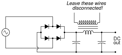
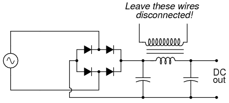
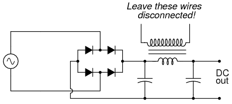
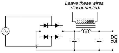
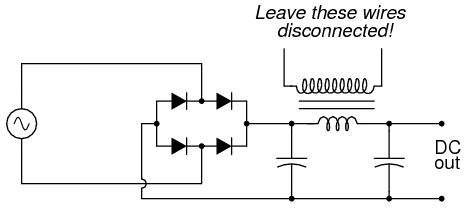
I didn't mean to buy one, I meant to build one. Should be pretty cheap, actually. I wouldn't try to parallel bridges. Large enough bridges are available. And don't use a resistor, use a choke as in the diagram below. If you can confirm that the motor is a permanent magnet motor, with no field coil windings, then we can get specific with the components. Treadmill power circuits use a choke. Too bad you didn't snag that too. There is a catch to this, but until I hear back from you on the specifics, we won't discuss it. One thing at a time.


05195.png

If you choose to build such a filter circuit, be sure to use an iron-core inductor for maximum inductance, and one with thick enough wire to safely handle the full rated current of power supply. Inductors used for the purpose of filtering are sometimes referred to as chokes, because they "choke" AC ripple voltage from getting to the load. If a suitable choke cannot be obtained, the secondary winding of a step-down power transformer like the type used to step 120 volts AC down to 12 or 6 volts AC in the low-voltage power supply may be used. Leave the primary (120 volt) winding open

05195.png

05195.png
 
Thanks for the responses Tony. As soon as I return home from the holidays with family, I'll get all the info I can feed you off the motor and we can proceed.Appreciate the help.
Jasper
 
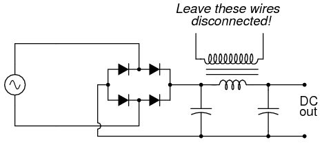
I didn't mean to buy one, I meant to build one. Should be pretty cheap, actually. I wouldn't try to parallel bridges. Large enough bridges are available. And don't use a resistor, use a choke as in the diagram below. If you can confirm that the motor is a permanent magnet motor, with no field coil windings, then we can get specific with the components. Treadmill power circuits use a choke. Too bad you didn't snag that too. There is a catch to this, but until I hear back from you on the specifics, we won't discuss it. One thing at a time.


05195.png

If you choose to build such a filter circuit, be sure to use an iron-core inductor for maximum inductance, and one with thick enough wire to safely handle the full rated current of power supply. Inductors used for the purpose of filtering are sometimes referred to as chokes, because they "choke" AC ripple voltage from getting to the load. If a suitable choke cannot be obtained, the secondary winding of a step-down power transformer like the type used to step 120 volts AC down to 12 or 6 volts AC in the low-voltage power supply may be used. Leave the primary (120 volt) winding open
......

http://s1206.photobucket.com/albums/bb457/Methuselah3/?action=view&current=100_0697-Copy.jpg

http://s1206.photobucket.com/albums/bb457/Methuselah3/?action=view&current=081.jpg

http://s1206.photobucket.com/albums/bb457/Methuselah3/?action=view&current=082.jpg

Tony,
Hopefully the above links will show the faceplate picture of the motor and a transformer. I went back to the scrapyard but couldn't find any electronic parts for the build. The 120 V DC permanent magnet motor has 4 leads. Two (red/black) go to the perimeter of the motor for the brushes and 2 leads ( blue) attach to what I presume is a heat detector circuit as they connect close to the end plate to a small common device on the housing. While at the scrapyard I picked up a transformer for possible usage.I have several oil filled capacitors mostly 60 µfd and at least 1 30 µfd that I've gathered for my phaser project but that's another story. Will start a new thread for that.On your diagram, I conclude the following. Left most symbol is 120 v AC.Rectangular with diodes is the bridge. Transformer is to be used if chokes not available???? and the cross connections are chokes??????. I tried to look for chokes and bridges on the internet but couldn't find any big enough as I thought you had described so you may have to rub my nose on the location for me to see them and give me numbers for amps/volt ratings required.I saw some small "torroidal" chokes on the computer boards at the scrapyard and wouldn't have known what they were except for my attempt at research on the web. Thanks for your help.
Jasper

05195.png

05195.png
 
Back
Top