- Joined
- Jun 16, 2016
- Messages
- 221
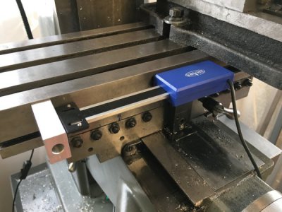
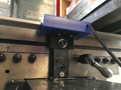
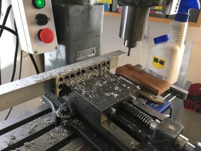
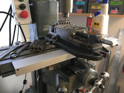
Now that my recently-acquired mini-mill is up and running, I've started using it to make the mounting hardware for digital scales. I'll be installing a full set of Shars scales and using Yuriy Krushelnytskiy's "TouchDRO" hardware and Android app. I've already set up my Logan Model 200 lathe with TouchDRO, and love it.
I started with the quill scale, figuring that it would be the most difficult given the limited space. First to go were the factory mounting brackets. There simply wasn't room for them. After a lot of measuring and sketching I came up with a scheme for two L-shaped brackets, and only one needed to be bent. A flat "moving" bracket would attach the read head to the quill stop, and a "fixed" bracket with one 90-degree bend would attach the top end of the scale to the mill's head. The bottom end of the scale would float. I had already successfully used a similar approach on the X axis for my lathe DRO.
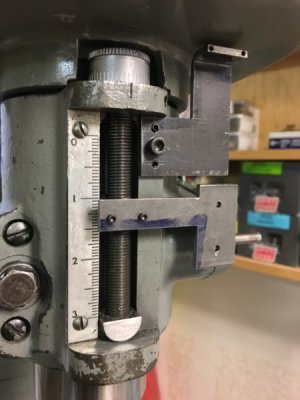
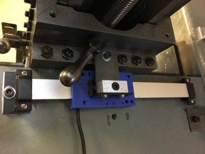
I milled and bent the brackets from 1/8" mild steel, and this shot is of the initial fit check, to make sure things aligned properly and to mark the length of the top bend in the fixed bracket:
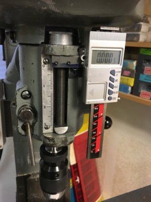
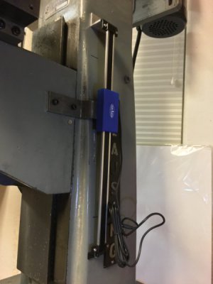
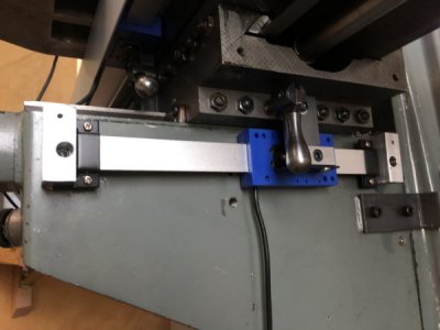
I can only use 3" of travel, so I cut the Shars 4" stainless vertical scale down using a cutoff wheel in my Dremel, then squared it up on my 6" x 48" belt sander. Piece of cake. After the fit check I milled the top end of the fixed bracket to align with the back face of the scale and drilled and tapped it.
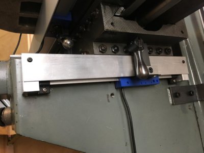
So much for the easy part. I don't own a drill bit that will touch this hardened stainless, so now I'm waiting for the cobalt and carbide to be delivered. Once I have the tooling I will be drilling the top end of the scale to match the fixed bracket.
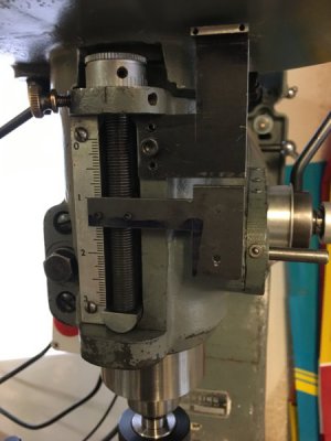
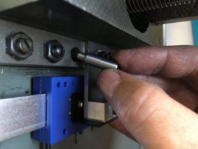
Marking, drilling and tapping the quill stop, in place, was a delicate hand operation, but went well. You can see the 2-56 cap-head screws that attach the moving bracket to it. To mount the fixed bracket the head was drilled and tapped for a single 10-24 cap head screw that you can see here just peeking out from underneath the moving bracket. After aligning and tightening the fixed bracket I drilled for two 1/8" anti-rotation roll pins, one of which you can just barely see here.
Once everything is assembled, aligned and tight I will install 1/16" roll pins in the moving bracket/quill stop and the fixed bracket/scale so that the 2-56 screws aren't shear-loaded and to stiffen things up.
I apologize for the verbiage. Pictures will be much easier to understand, and I'll be posting more detailed shots over the next few days if life doesn't get in the way.
I started with the quill scale, figuring that it would be the most difficult given the limited space. First to go were the factory mounting brackets. There simply wasn't room for them. After a lot of measuring and sketching I came up with a scheme for two L-shaped brackets, and only one needed to be bent. A flat "moving" bracket would attach the read head to the quill stop, and a "fixed" bracket with one 90-degree bend would attach the top end of the scale to the mill's head. The bottom end of the scale would float. I had already successfully used a similar approach on the X axis for my lathe DRO.
I milled and bent the brackets from 1/8" mild steel, and this shot is of the initial fit check, to make sure things aligned properly and to mark the length of the top bend in the fixed bracket:

I can only use 3" of travel, so I cut the Shars 4" stainless vertical scale down using a cutoff wheel in my Dremel, then squared it up on my 6" x 48" belt sander. Piece of cake. After the fit check I milled the top end of the fixed bracket to align with the back face of the scale and drilled and tapped it.
So much for the easy part. I don't own a drill bit that will touch this hardened stainless, so now I'm waiting for the cobalt and carbide to be delivered. Once I have the tooling I will be drilling the top end of the scale to match the fixed bracket.
Marking, drilling and tapping the quill stop, in place, was a delicate hand operation, but went well. You can see the 2-56 cap-head screws that attach the moving bracket to it. To mount the fixed bracket the head was drilled and tapped for a single 10-24 cap head screw that you can see here just peeking out from underneath the moving bracket. After aligning and tightening the fixed bracket I drilled for two 1/8" anti-rotation roll pins, one of which you can just barely see here.
Once everything is assembled, aligned and tight I will install 1/16" roll pins in the moving bracket/quill stop and the fixed bracket/scale so that the 2-56 screws aren't shear-loaded and to stiffen things up.
I apologize for the verbiage. Pictures will be much easier to understand, and I'll be posting more detailed shots over the next few days if life doesn't get in the way.


