Can This Motor Be Electrically Reversed ???

extropic

H-M Supporter - Diamond Member
H-M Lifetime Diamond Member
Joined
Nov 24, 2014
Messages
3,152
I want to temporarily reverse the rotation of an import drill press. I bought it used, so am not sure of it's country of manufacture. Probably China, maybe Taiwan, I doubt Japan. I understand that "instant reverse" isn't possible with this type of motor and that's OK. I'll power off and bring it to a dead stop before changing direction.

There is a single, metal cased, 300µF capacitor mounted to the exterior of the motor housing so I presume it's a capacitor start/induction run motor.

The first picture is of the back side of the terminal block (normally mounted on the outside of the motor housing). It has four circuits. The green wire is ground and disconnected from the motor housing when I took the photo. The green ground wire isn't connected to the terminal block. the black and white wires are 120 V line. The blue wires are jumpers. The four wires opposite come through a grommet from the interior of the motor.
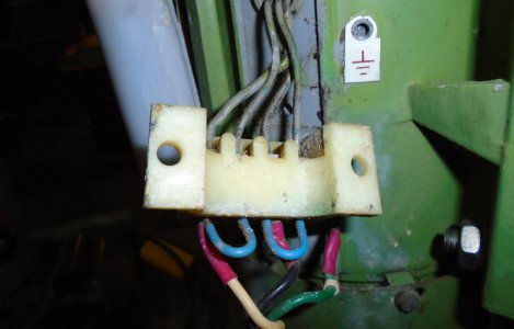
Motor Terminal Block.jpg

The second picture is of the motor nomenclature plate. The upper right hand box didn't photo well. The nomenclature in that box is 370 followed by a printed character (unit?).
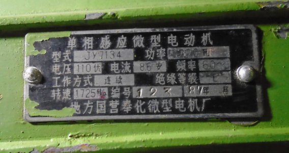
Motor Name Plate 1.jpg

From what I've read so far, if I reverse the start winding I'll reverse the motor rotation. It's possible, AFAIK, that two of the four wires passing through the motor housing, to the terminal block, are for run windings and two are for the start winding. Am I right about that? How can I tell (without doing damage to the motor)?

I don't want to dismount and open up the motor unless absolutely necessary. If it can be reversed by rearranging any of the wiring that you see in the picture of the terminal block, I'll probably hook up a toggle switch to accomplish FWD - REV change.

TIA
 
Last edited:
If the two windings have different resistances, one is probably the start. Also the nameplate doesn't indicate that it's a dual-voltage motor, so there should only be one run winding. Your plan should work.

The nameplate is Japanese.
 
It is difficult, if not impossible to tell from just a photograph of some wires. A wire trace is in order; preferably with an ohmmeter.

Assuming single voltage operation, one pair of black wires may be the run winding and the second may be the series start winding/capacitor/switch circuit. If so, reversing the connections of the blue wires may reverse your rotation. Jumper 1 & 4, 3 & 2. But I would definitely want to trace the wiring first.
 
If the two windings have different resistances, one is probably the start. Also the nameplate doesn't indicate that it's a dual-voltage motor, so there should only be one run winding. Your plan should work.

The nameplate is Japanese.

Thanks for the info Alan. If the machine is Japanese manufacture (I believe the motor is original), I think that's good news for me.
 
It is difficult, if not impossible to tell from just a photograph of some wires. A wire trace is in order; preferably with an ohmmeter.

Assuming single voltage operation, one pair of black wires may be the run winding and the second may be the series start winding/capacitor/switch circuit. If so, reversing the connections of the blue wires may reverse your rotation. Jumper 1 & 4, 3 & 2. But I would definitely want to trace the wiring first.

Thanks for your reply.

I have a good multimeter but am not certain what to do with it in this case. Can you describe what you mean by a wire trace? What would I be looking for?

Alternatively, what is the risk of modifying the jumpers as you describe? If modifying the jumpers didn't simply reverse rotation, what is the probability of doing damage to the motor?
 
If the two windings have different resistances, one is probably the start. Also the nameplate doesn't indicate that it's a dual-voltage motor, so there should only be one run winding. Your plan should work.

The nameplate is Japanese.

My bad for not fully address all the info you provided in my previous reply.

Yes, only single voltage motor.

I'll do a continuity check across all pairings of the four wires and note the resistance found. I was thinking that if I rotate the armature (using a cordless drill to drive it) I can identify which pair is the start circuit because the switch should open the circuit at about 1300 RPM. If that's what I find, I'll have pretty good confidence that I understand what's going on and how to proceed.
 
I should have mentioned that if one pair of wires is the start winding, it will be in series with the capacitor (and switch) so you won't get a low resistance reading. You should see a momentary low reading (easier to see on an analog rather than a digital meter).

Risk of damage is essentially zero.

Yes, my multimeter is digital (Fluke 77).

I presume it's the capacitor that will prevent seeing low resistance through the start circuit. This capacitor is connected with solder terminals so I could unsolder one lead and connect it to the other for the purposes of a continuity check. I feel like I'm going the long way around now (as my confidence (understanding?) grows) but I keep telling myself to error on the side of caution. Don't want to let the smoke out.
 
Hi extropic,

My first thought was to simply put a twist in the belt to make the secondary shaft turn the other direction.
If it's temporary the belt rubbing by itself won't do damage. You may need a longer belt.

Initially it sounded like you had no easy access to the internals of the motor. That would make tracing all the wires more difficult.
Now that you say you could de-solder the capacitor, then we're in business.......

First, since all the wires look the same, I'd label them so you can get back to your starting point.
Then take some more pictures showing the labelled wires.

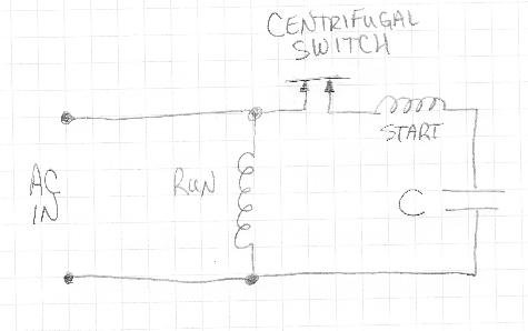
If it is a single-voltage, capacitor start motor with a centrifugal switch, then the basic circuit should look like this:
ScreenShot170.jpg
Note that since the centrifugal switch, start winding and capacitor are all in series, they could be in any order and still work the same.

Anyhow, if you can now trace which is the start winding then reversing the motor direction should be just a matter of reversing the two start winding wires.

error on the side of caution. Don't want to let the smoke out.
:encourage:Keep being cautious!:encourage:
Most important is not hurting yourself, secondary is not damaging the motor.
Double check it's unplugged before measuring continuity/resistances or getting your fingers in there.

I believe all the above is correct, however, treat this as you should any (semi-)anonymous advice form the internet!

-brino
 
Thanks for your reply.

I have a good multimeter but am not certain what to do with it in this case. Can you describe what you mean by a wire trace? What would I be looking for?

Alternatively, what is the risk of modifying the jumpers as you describe? If modifying the jumpers didn't simply reverse rotation, what is the probability of doing damage to the motor?
You should temporarily disconnect the jumpers. Connect one lead of the ohmmeter to one of the wires and probe the remaining wires. I would expect continuity between wires 1 and 3 as that is where your line is connected. Wires 2 and 4 hopefully will lead to the centrifugal switch, the capacitor, and the start winding as shown by brino above.

Note that a capacitor will show open with an ohmmeter. It will show some initial reading but it will increase with time, the rate determined by your meter.If you are able to access the capacitor, see if you get continuity between one of the capacitor terminals and one of the wires on your terminal block. Then check for continuity between the other capacitor terminal and the wires on your terminal block. If you do get continuity, you should see a difference in the resistance. One should be close to zero, the other should be some low ohm value. That would be a fairly good indication those two wires are the start circuit.

Murphy's Law still rules. Ideally, I would want to identify all the connections in the start circuit. However, if you are reasonably sure that wires 2 and 4 are connected are connected to the capacitor, you should be OK. At this point, I am assuming that your motor is running and when it starts turning, you hear the centrifugal switch kick out. If you reversed the two leads and it was wired properly, the motor should start rotating in the opposite direction and the capacitor should kick out. If you connect power to the motor for a second or two, it is not likely that you would see any damage. If it doesn't begin to rotate immediately or if it just hums, disconnect the power immediately.
 
Back
Top