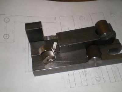
Camjack Knurler

Hawkeye

Active User
H-M Supporter Gold Member
Joined
Jun 17, 2011
Messages
2,069
Okay, guys. A couple of months ago, I mentioned a Project-in-Waiting that I called a Camjack Knurler. When you invent something, you're allowed to make up words, too. It came about because I had checked out several sites on clamp knurlers. Most seem to use a 6 mm threaded shaft to apply pressure, but some commented that it didn't have enough force for steel. This tool has plenty of pressure, easily controlled.

Members of this forum may use this principle to build their own, but, of course, may not profit from my design.

Here's a look at the finished product in use, mounted in the QCTP. The bar on the top with the 1/4" jack screw is the camjack. When the tail is raised with the jack screw, the camjack pivots around the opposite end and pulls up on the 1/2"-20 main screw. It provides more than 5 to 1 mechanical advantage. The knurl arms are pivoted farther away from the roller ends than normal. This unit is designed for up to 2" knurled work.
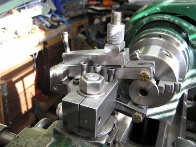
PA160049.jpg

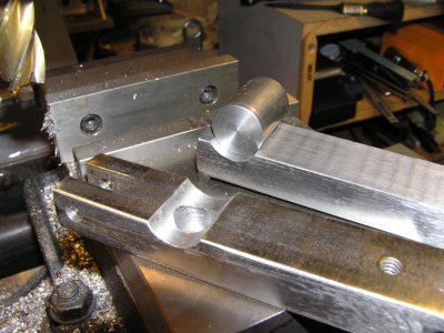
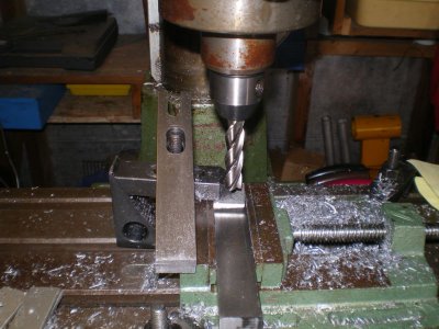
Jumping back to some of the construction details. The bottom bar and the camjack are clamped in the vise with a piece of 3/8" aluminum between them to plunge-mill the depressions for the 3/4" main screw pivot blocks.
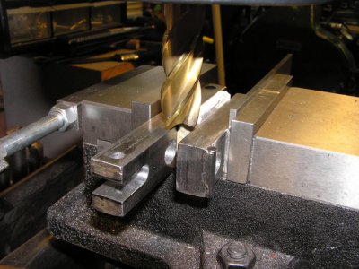
PA150039.jpg

PA150041.jpg

The axles for the knurls were turned from a pair of 5/16" grade 8 bolts.
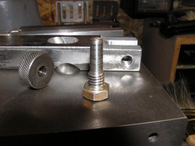
PA150043.jpg

The complete tool is set up for the test cut. The 1/2"-20 main screw works well with a lug nut as the adjusted. This is turned hand-tight once the crossfeed is centered on the work, with the camjack all the way down. Then the jackscrew is tightened with the work oiled and the lathe running at knurling speed. Enough pressure can be applied by hand that I may just add a knurled top on the jackscrew.
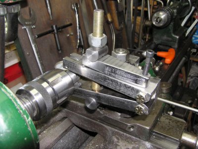
PA160046.jpg

I'm quite pleased with the way it works. This will, of course, be the main screw nut. It has to have a knurled one, doesn't it? (See the top photo.)
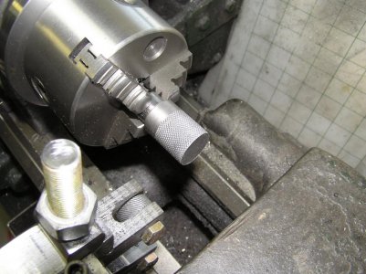
PA160047.jpg

PA160049.jpg PA150039.jpg PA150041.jpg PA150043.jpg PA160046.jpg PA160047.jpg
 
Nice job Mike.:cool:

I especially love the wheel nut you used temporarily on the main screw.:D
 
Mike, that is one heavy duty knurler! I know that puppy applies some serious pressure to those rollers, because I have a different tool that uses that principle for separating the taper on ball joints. When they let go, they do it with a BANG!

Great job, and great idea. Well done Sir!

View attachment 667
 
Sorry, Mayhem. No plans. Just a basic CAD sketch to work out a few ideas. Funny thing was, I zoomed in on the layout I wanted and printed Display onto an 8 1/2 x 11 sheet. When I laid the L-shaped mounting arm on it, it fit exactly. All I had to do from there was measure off the drawing. Nice when a 'plan' comes together.

For reference, the arms are 1" x 5/8" bar stock 5" long. Material is MU (Magnetic Unknownium - not to be confused with the nastier Ferrous Unknownium). The knurls were taken from my cheapy bump knurler.
 
Congrats

Nice design and execution. I intend to copy it. I have worn out the bump knurlers that came with my toolpost sets, The knurls don't like stainless.
Joe
 
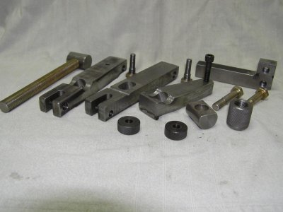
Okay, Mayhem, here's the individual pieces of the knurler. It's a bit more work to post without the buttons, but I'll try.

All of the pieces are shown. I did try a spring on the main threaded shaft, but it kept getting jammed up in the slots, even with washers in place.
PA210002.jpg

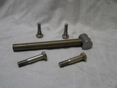
The threaded parts. The jackscrew is not shown in this one. The main shaft is 1/2 - 20. It's swivel is threaded and held in place with strong threadlocker. A smaller shaft diameter would likely work, but I wouldn't go any smaller than 3/8". Fine thread is recommended.
PA210003.jpg

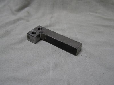
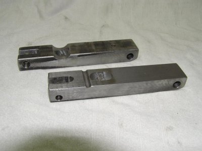
The mounting arm was the first part made, some time ago. Most clamp knurlers are completely on the work side of the toolpost. I figured longer arms pivoted from behind the post would give better control.
PA210009.jpg

The arms are 5" long. The bottom one has a 3/4" diameter swivel groove. Both have 1/2" slots to allow the main shaft to swing to suit diameters of work up to 2". The upper arm has a 3/16" diameter slot for the camjack fulcrum.
PA210004.jpg

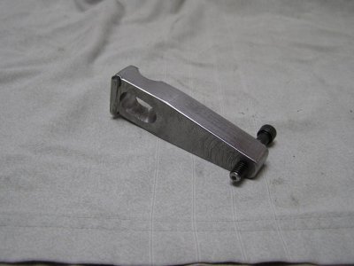
The key to the power of this knurler is the camjack. The fulcrum is a piece of 3/16" music wire welded into a milled slot at the end. The end of the jackscrew is rounded to allow it to move on the flat surface of the upper arm.
PA210005.jpg

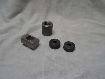
Final parts include the knurled (of course) main shaft nut, diamond knurls and the upper shaft swivel.
PA210010.jpg

Have fun making your own version of this tool. I'm very pleased with the way it works.

PA210002.jpg PA210003.jpg PA210004.jpg PA210005.jpg PA210009.jpg PA210010.jpg
 
Mike/Hawkeye(MASH, in my top 3 tv faves! :)) thanks for posting this! Once I get my lathe I need to do some serious knurling so I'm going to try to build this. It's a Franken-knurler! :)
 
Okay, guys. A couple of months ago, I mentioned a Project-in-Waiting that I called a Camjack Knurler. When you invent something, you're allowed to make up words, too. It came about because I had checked out several sites on clamp knurlers. Most seem to use a 6 mm threaded shaft to apply pressure, but some commented that it didn't have enough force for steel. This tool has plenty of pressure, easily controlled.

Members of this forum may use this principle to build their own, but, of course, may not profit from my design.

Hawkeye,

Thanks for the design. It's a great idea. I put it on my list of want-to-builds. I don't know how I missed it when first posted.

Benny
 
Hawkeye and I discussed me releasing a set of drawings for this and he was gracious and generous enough to say go ahead with a few common sense exclusions !not for commercial use! Use at own risk.

I'm not quite ready to release the drawings yet. Things are moving a little slow in testing them since I had a hernia repaired and my gall bladder removed 2wks & 3 days ago. The doctor allows me to lift 15#s now but that still leaves me using the HF drill press vice. I just want to make sure that if someone orders material and the parts don't fit it's their own dang fault and not the drawings.

15# vice.JPG

It is so much like clamping work on the table with that vice.

deplanbossdeplan.JPG

Here's is what I have done so far sitting on full size drawings.

Steve

15# vice.JPG deplanbossdeplan.JPG
 
Really nice job on this. I bought one of these a few years back. Big mistake I should have just made one. Maybe your post will inspire me to make a new one. I like your design better than the one I bought by miles.

Jeff
 
Back
Top