Building A Z Axis Head On A Universal Mill.

Str8jacket

H-M Supporter - Gold Member
H-M Supporter Gold Member
Joined
May 17, 2015
Messages
165
G'day

Posted up a while ago in the general section but Im getting closer to collecting all the bits and pieces and have some questions before I go to mauch further. A bit of background.
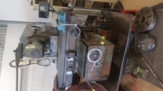
I have a large universal mill, want to build a Z axis head that I can use manually or in NC mode, not at full cnc needs yet.

I have a 5HP vector duty motor and a 10HP control techniques drive that has option to fit with a 1.5axis motion control for the spindle, the motor is 230V 3phase and the drive is 400V which is my power supply, I have done the research on this and have done a similar conversion on my lathe so am fairly confident with this part.

Not sure what is the best way to attack the servo drive set up? I have picked up control techniques servo drive and an AC servo motor rated to 3000rpm and 7.7Nm coupled to a 7:1 precision gearbox. Its all brand new, cables and all. But is it too big?

The next part of the equation is the spindle head, I need to buy a BT40 head off a VMC and machine a carriage to hold it, belt driven off the motor, I have questions on the drive ratio needed there.

Now I don't know if I should solid mount the motor and drive a ball spline shaft to the belt pulley to allow z axis movement of the spindle head only or build a carriage with large hiwin linear rails to carry the whole lot like on a cnc VMC?

How do I size the the ball screws? I am goind to use this as a powered z axis feed for general machining but I would also like the option of using it in semi manual mode to use similar to a drill press (on steroids)
Is this possible?

Cheers Str8.
 
Last edited:
Well the research continues, looking at a few different manufactures online calculators for ball screws it appears that something around the 25mm-32mm diameter with a 5mm -10mm lead will be sufficient. I have seen some cnc VMC z axis's with a 16mm lead but that would be getting to speeds I don't think I would need. This is on the assumption that my assumptions for the calculator are correct.

Any opinions on travel that would be practical and needed? I'm thinking 6in min to around 12in or if I'm going to the effort should I go more?
 
What you ask is.... difficult.

From my POV, you might be approaching your design somewhat backwards. What's too big? What's too small? First you gotta know what YOU are gonna do. Are you gonna chuck up a 2" 4 flute and go hogging through Stainless? Or are you gonna use a 1/4" cutter for making plastic signs? That, i think, should be your big driver.

Then after deciding a mission profile, you may wish to determine, yourself, just how much and what type of Z-travel interests you. Do you just need enough to get that 1/2" cutter out of the plastic? Maybe 1/2" of travel? Or are you back to moving 5-6" out of that big pocket? Or are you boring 10" deep holes? This all matters. Because, yes, you might want some little short rails and you might want some quill either one... or both. But of course, the side loading on that quill increases with the *square* of the distance. So if a 1" protrusion is 1,000 lbs, then a 4" protrusion is not 4,000 lbs, but 16,000 lbs. Adds up fast.

From what i can discern, it sounds like the mill is already solid and hearty in Z. If so, a small screw should more than suffice until you want to start really heavy 3D contouring. And, because i'm not shy about counting the weight of the moving head, it would still suffice because all it's really doing is hauling the head out of the way. If the head is already on its own stout rails, then all you need with the screw and such. That head might weigh-in at 800-1000 lbs or more, depending on your model of mill, and that would be pretty stable for cutting with a smallish endmill (1" ballnose) on just inertia alone.

Design a mission parameter. I want to make these kinda cuts with these kinda removal rates through these kinds of materials. From that you can find hp requirements (at the cutter) and loadings in all directions. Or, you just wanna max out everything -- full hp from the existing spindle motor. Whatever. Don't know. From that you can make a more appropriately informed decision on hardware.

Then the fun really begins ;-)


Wrat
 
Hi Wrat,
Thanks for your reply, my mill has a fixed head and Z on the knee. It is a BT50 arbor.
It does big:D my biggest face mill, im only starting to tool up, is an 8 insert 80mm and i havent done a cut big enough to register on the spindle amp meter yet.
Initially I was going to by a bridgeport head and fit that. But it was going to be about $4k going a new clone or $3k for a whole second hand machine. No wreckers here.
So i had a good motor here that i can run upto nearly 10hp at 120hz 3600rpm. I have the vfd to drive it.
Ive got a AC servo motor and drive that should run a whole vmc style z axis head.
So far Im $600 in. So thought what the hell, maybe i can build my own. If its a failure i can always use the bits on something else and Im learni g on the way.
As far as a mission brief. Every job I try and do is always a bit bigger than the gear Ive got to do it. I need the ability to run atleast a 50mm rotabroach for drilling.
Drill a 24mm hole with a normal drill

Id like to be able to use it to bore atleast 6in holes. But after reading your post im thinking no quill. Build the whole lot to move, my servo will do it.

Id like to be able to use a 1/4in endmill at full speed. My head now only goes to 1400rpm.

Ive been looking at bt40 spindles that will do 8000rpm. I would be doing mainly steel and aluminium.

Where i am machining isnt cheap. Surrounded by mines that just fork money over. I have to get work done 1000klms away before the price becomes reasonable. So if i spend a bit more now and can do my own stuff later I am willing to pay for it. Plus the odd job here and there will help as i have virtually no competition in the one off small jobs market. Plus i dont have much spare time to waste watching a small machine struggle, if i can have something that will rip through it. :p

I was thinking maybe a xy table cnc later down the track to fit on my table.

Does that list of impossible wants help in any way? :D
 
I wouldn't use the word "impossible", but i might use words like "expensive, troublesome, and unrealistic". Th ROI of such an effort would be small for a long time.

Z on the knee means you're probably moving at least 1,000 lbs. So that "AC servo motor and drive" will need to be big. As will the ball screw.

You know, some pics wouldn't be the worst thing.

Maybe look into your own suggestion. See what you can do with XY. Even if it came down to a "daughter-table". That is, building an XY positioner that simply bolted into place on your regular table in much the way you might do a rotary table. Get THAT all worked out with controller and such and enjoy a few advantages, there. Still run Z by hand. 2 axis NC is still a lot of capability, especially for profiling and small jobs.

That way, you're not looking at jumbo ball screws and motors to drive them. Nor are you looking to retrofit bearings and stops. At least not just yet, anyway.

And if your head goes *all the way* up to 1400 rpm, it might be time to first look into a geared add-on for 1/4" work. Seen an old boy build one of those himself and use it. Bolted onto the snout of his machine.


Wrat
 
I apologize if others have mentioned this before, but something I have seen in my very limited experience with moving the knee on a CNC conversion is to counterweight the knee so the ball screw doesn't have to support it.


Steve Shannon, P.E.
 
Thanks guys. Im not going to do anything with the knee. All axis's are currently powered as it is. The knee is just not made for drilling etc. The gear box doesnt even like trying to rapid it up. And trying to manual lift it by hand is hard work for anything other than fine tuning. At a guess the knee would be close to 2500 pounds. The whole machine is nearly 7000pounds.

What im looking at doing is swinging the vertical head out of the way and bolting on my own.
 
something I have seen in my very limited experience with moving the knee on a CNC conversion is to counterweight the knee so the ball screw doesn't have to support it.

Where and how??

I mean, sure you've seen it, but look at the pix, where would you hang a 2000 lb counterweight? Thus turning an 8000 lb machine into a 10,000 lb machine, I might add.

It's a sound principle, it's just a wildly difficult application to solve. [Not trying to be confrontational, just deathly curious if you had a concept that came to mind.]

As it happens, I own that machine's daddy. Same setup, 30 or 40 years older. And yes, i've had irresponsible dreams of applying CNC to it, myself.

What im looking at doing is swinging the vertical head out of the way and bolting on my own.

Okay, now i'm keeping up. That's actually not a bad quest. Sounds like most of a plan already.

Build the daughter table. You gotta have XY, anyway and that get all your basics covered and adding a Z is no big deal. Lots of solid knowledge on the forum about that.

Hang a new head. It needn't be Bridgeport, but could be any of a thousand designs including a router head. Just a rail or two or whatever you end up finding. The lighter the new head, the easier to get full motion going for it so you're back to deciding how heavy you want this to be. Plug it into your XY controller at the Z output port. [well, there's more to it than that, but you get the idea.]

Now, you've got a super-rigid mini CNC setup. Okay, essentially, you're building a CNC machine on top of your machine -- and you might ultimately be ahead to move the whole workings to its own pedestal, that you'll have to build, also, but at least you got the machine to that part already.

Point it, this way you can build it up and be productive along the way. Eat the elephant one bite at a time, as it were.

Wrat
 
Well my Z axis servo setup arrived today and it is far more hefty than I anticipated. I found it on ebay make an offer so I threw out a low ball to see what happened and got it, arrived in Oz for a total of $400, Control techniques AC servo drive, cables and AC servo motor 2.4kw with a precision planetary box, all brand new, the servo drive even has a high speed communications adaptor. pretty stoked.

The servo has a the following Mn 68lbin and Mcs 90lbin

I had used a calculator online for servo sizing and it come up with a really high requirement for torque. I don't think it is right. This servo with out the reduction box is 1088ozin torque and 1440ozin stall if I am understanding correctly? This seems to be a bit more than most recommendations for mini mill builds I've seen but I am estimating the head will weigh around 175 pounds if I combine the weight of the 5hp spindle motor and the spindle and mounts rails etc.

So I am thinking that with this much grunt I will either have too much power and am unsure on the ramifications of this or it will be able to move the head with enough power that I can choose a ballscrew with any lead from 5mm to 16mm and be ok. Ahh I wish I had done better at school and I could have been an engineer and not a diesel fitter!

Servo problem 2..... It doesn't have a built in brake. What are options for brakes on the screw?
 
Back
Top