Building a steady rest

Mark_f

Registered
Registered
Joined
Jan 16, 2020
Messages
5
I started building a steady rest for my south bend 9 inch lathe. I am trying to build it with the telescoping (or co-axial, for some people) arms instead of the "cheapie" flat fingers sliding in a slot. The arms will be quite a project me thinks. If there is interest, I will try to post the progress here. I hope to have a 4 inch capacity instead of 3 as the factory made them, so I had to alter some dimensions from the factory prints.

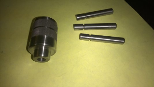
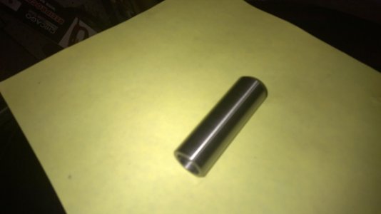
Today I started the telescoping assemblies for the steady rest. I am going to make all three of these before I machine the frame in case these are a bust and I have to make the "cheapie" arms that slide in a slot. I want to make sure they work and that I get the travel I want before I cut the hole. I am hoping for two inch travel, but will cut the hole for the maximum travel I end up with. I lengthened the knob and sleeve .250" more than the SB prints called for. I will also lengthen the brass fingers as it is much easier to cut excess off than try to add back on.
The screws aren't threaded yet because I am waiting for the 3/8-16 left hand tap and die from Victor Machinery. They were only $12 for both. I threaded the knob , but not the sleeve yet. I used a tap on the knob and the threads are really nice. I want the threads on the sleeve cut to fit the knob so I will do them on the lathe. I want a tight fit ,but smooth turning. Tomorrow I will make the other two knobs and start on the brass fingers. Then thread the sleeves.


Mark
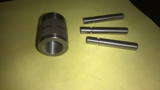

knob and screws for steady rest 2.jpgknob and screws for steady rest 3.jpgknob and screws for steady rest.jpgsleeve for steady rest.jpg

knob and screws for steady rest 2.jpg knob and screws for steady rest 3.jpg knob and screws for steady rest.jpg sleeve for steady rest.jpg
 
Mark
How is the steady rest coming? I thought I had replied back when I first saw your project but my absent mindedness I did not. But I did page make to come back and, well I guess no one else showed any interest in the steady. Did you finish it or is it still in progress?
Cheers
Nelson Collar
 
I must have missed this when it was first posted. It makes no difference what lathe a steady rest is for. it can be adapted to any lathe of any size. Yes there will certainly be interest in this project. Please keep us updated on you progress.

"Billy G"
 
If you need a draw let me know I have one in a DWG file
I started building a steady rest for my south bend 9 inch lathe. I am trying to build it with the telescoping (or co-axial, for some people) arms instead of the "cheapie" flat fingers sliding in a slot. The arms will be quite a project me thinks. If there is interest, I will try to post the progress here. I hope to have a 4 inch capacity instead of 3 as the factory made them, so I had to alter some dimensions from the factory prints.

Today I started the telescoping assemblies for the steady rest. I am going to make all three of these before I machine the frame in case these are a bust and I have to make the "cheapie" arms that slide in a slot. I want to make sure they work and that I get the travel I want before I cut the hole. I am hoping for two inch travel, but will cut the hole for the maximum travel I end up with. I lengthened the knob and sleeve .250" more than the SB prints called for. I will also lengthen the brass fingers as it is much easier to cut excess off than try to add back on.
The screws aren't threaded yet because I am waiting for the 3/8-16 left hand tap and die from Victor Machinery. They were only $12 for both. I threaded the knob , but not the sleeve yet. I used a tap on the knob and the threads are really nice. I want the threads on the sleeve cut to fit the knob so I will do them on the lathe. I want a tight fit ,but smooth turning. Tomorrow I will make the other two knobs and start on the brass fingers. Then thread the sleeves.


Mark
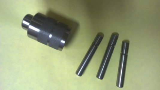

View attachment 81652View attachment 81653View attachment 81654View attachment 81655
 
Well it has been a while, but I am back on the steady rest project. The left hand tap came in this week and so did the brass for the fingers. I took a break while waiting and finished up some other projects that were started and made a few other things. It was a good thing As I sat down a few times thinking about the steady rest and discovered the change from 3/8-10 threads that S.B. used to the 3/8-16 threads meant a change in the length of the fingers and sleeves. They have to be at least 1/4 inch longer. If I had made them before they would have been wrong.
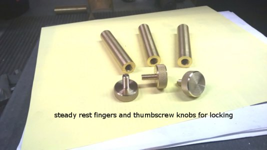
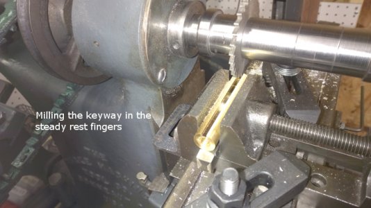
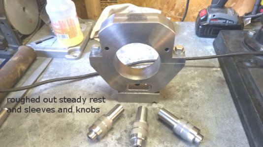
The last couple days I made the brass fingers and new sleeves. I also made the thumbscrews that lock the fingers. S.B. made these from steel , but I am trying brass because it looks sooo much prettier. Here are some photos of the new parts.

fingers and thumbscrews.jpg


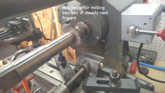
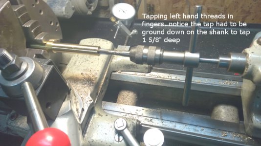
The brass fingers have the left hand threads done. I had to grind the shank of the plug tap and bottom tap down to reach the 1 1/2" thread depth needed.

mill setup for steady rest fingers.jpg

steady rest finger keyway.jpg

tapping fingers.jpg

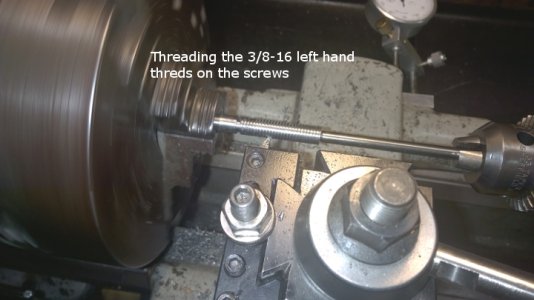
I will be putting the left hand threads on the screws with the lathe as they need to be a good fit. I have an adjustable die , but the lathe will do a better fit and I only want to make these once.
this week I plan on threading the new sleeve on the lathe also. They are 7/8-14, threading half of the 3 inch sleeve.

This has turned into an interesting project. It started by someone (on another forum) a while back, telling me it was a bad idea and probably too difficult and that I should buy one of the cheaper units with the adjustable fingers with bolts. At that point IT WAS ON! I will build this no mater how long it takes.
this is the type I want but they are very costly when you find them. Mine will have 1/2 inch more capacity, be much heavier and sturdier and so far I have about 60 bucks in it and I have all the material now. The hardest thing was getting the specs ( fortunately someone emailed me a set of South Bend Prints) and then figuring the changes needed by changing the threads as this altered many dimensions.

I will keep you posted on my progress

Mark

roughed out steady rest.jpg fingers and thumbscrews.jpg mill setup for steady rest fingers.jpg steady rest finger keyway.jpg tapping fingers.jpg
 
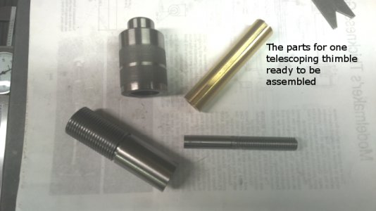
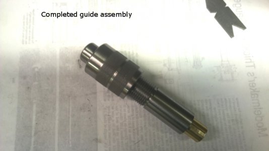
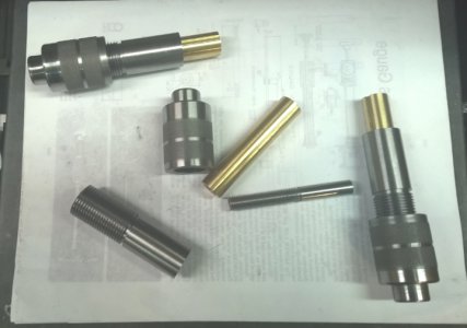
Today I completed the telescoping guide assemblies. I threaded the new sleeves to math the knob thread. All the threads in these assemblies are close fit. Tight but turn smoothly with ease. the diameters of the fingers, sleeves and screws are all within .0005 of one another and the print dimension. This makes all these parts interchangeable with one another and replacement parts can be made to the print and they will fit. The only concern I had was threading all these parts in the 3 jaw chuck which has about .002 run-out, I was concerned that the assemblies would be to tight or have tight spots because .002 on each part could add up to .004 to .006 per assembly. After doing the first assembly I found the fit was good and the error cause negligible problem. all three completed assemblies work great and I wound up with 2 inches of travel. This leaves wear room for the fingers as I needed 1.750 travel for the fingers to meet in the center. Here are photos of today's progress.

Thanks for watching,
Mark

Thimble parts.jpg
completed guide assembly.jpg
Steady rest guides comleted.jpg
threading the screws.jpg

Thimble parts.jpg completed guide assembly.jpg Steady rest guides comleted.jpg threading the screws.jpg
 
beautiful and impressive work - looking forward to the rest!
 
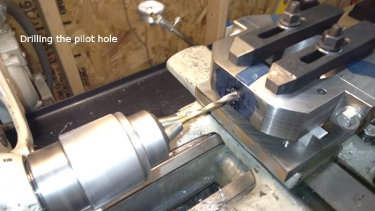
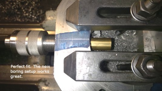
Well , boy and girls , it is really starting to look like a steady rest. Today I made a boring head to bore the holes for the telescoping assemblies. there will be more about that in a separate thread. I got all three holes bored and a perfect fit.

drilling the pilot hole.jpg I set up my milling table on the lathe and started by drilling a pilot hole
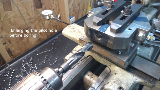
Enlarging the pilot hole.jpg I then enlarged the pilot hole to 3/4 inches
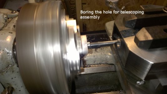
Boring for the thimble.jpg using my new boring setup, I bored the holes to a perfect fit.
perfect fit in bore.jpg
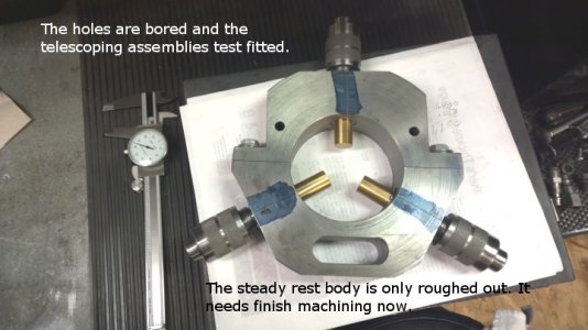
Thimbles test fitted.jpg The steady rest main body is only roughed out and now needs to be finished . I wish I could have it Blanchard ground , but there is no one around anymore that does that. All the machine shops in this area are gone. Guess I'll have to figure something else out.

thanks for watching,

Mark

drilling the pilot hole.jpg Enlarging the pilot hole.jpg Boring for the thimble.jpg perfect fit in bore.jpg Thimbles test fitted.jpg
 
Mark
It is starting to look real good. Nice machine work and process. Love that milling, keep up the good work.
Nelson Collar
 
Back
Top