Brake cam and handle for Clausing 8520, 8525, 8530, 8535 mills

Terrywerm

Registered
Registered
Joined
Jan 16, 2020
Messages
8
Some time back I promised member 34_40 that I would make him a brake cam for his Clausing 8520 mill, as his is missing. A piece of 5/8" W-1 stock is in the Keller at this very moment, cutting off a piece from which I can make the brake cam. I promised him that when I got around to making the new cam that I would include pictures and a short thread on making the part.

It is a very simple and straight forward part, but would be a good project for a budding machinist. For the benefit of others, I have included a drawing of the part including all dimensions should anyone ever feel the need to make one of their own.

View attachment CLAUSING 8520 BRAKE CAM.pdf


ON EDIT: I found a mistake on the drawing. I have the overall length of the brake handle listed as 4" but it should only be 3". Must have been using one of those upside down rulers again!
 
Last edited by a moderator:
I saved the print "just in case"! :))

Thanks so much!
 
Terry,

Suggest uploading the PDF to Clausing/Lathes. It looks like that function is working. I don't recall whether that folder is moderated or not and can't at the moment check. If it is, I'll release it as soon as Nelson has time to get those functions back.
 
Thanks Robert, good idea. I posted a document there yesterday about the bearings for the Clausing 8520 mills and had no problem.
 
Terry,
If it's not too much trouble, could you post pictures of the working end of the brake ?
Mine has the brake handle intact, but doesn't seem to do anything. Not sure if it's badly worn or missing something.
 
Terry,
If it's not too much trouble, could you post pictures of the working end of the brake ?
Mine has the brake handle intact, but doesn't seem to do anything. Not sure if it's badly worn or missing something.

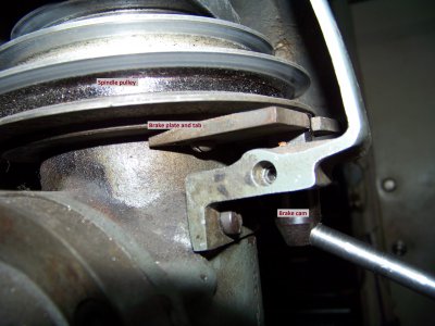
Here is the photo and a description of how it works, although it is rather self explanatory. Please pardon the fact that I have not yet cleaned and repainted this machine. Yup, she's a bit of a dirty girl!!:yeahbaby:

BrakeCam002.jpg

The brake plate as it is called in the parts list, is a split ring that sits under the upper spindle pulley. The plate has two tabs attached to it, and they straddle the brake cam. When you pull or push on the brake handle, the brake plate is pushed out against the pulley, stopping the spindle. Keep in mind that the pulley is made of aluminum, and it will soon wear away if the steel brake plate is used when the spindle is rotating. For that reason, I would avoid using the brake to stop the spindle, it usually stops pretty quickly on its own. I use mine only to hold the spindle when I need to do so.

The brake cam itself is retained by a setscrew that engages a groove in the cam. There are two setscrews in there, with one locking the other in place. Obviously, the first screw only engages the groove, and does not get tightened against the cam. Without the second setscrew, the first one would eventually rattle out due to vibration.

BrakeCam002.jpg
 
Last edited by a moderator:
I also made the new brake cam for 34_40's machine. The cam is made, but I still need to make the handle for it. Needed a chunk of 5/16" rod and didn't have any, so I need to pick some up before I head for work today.

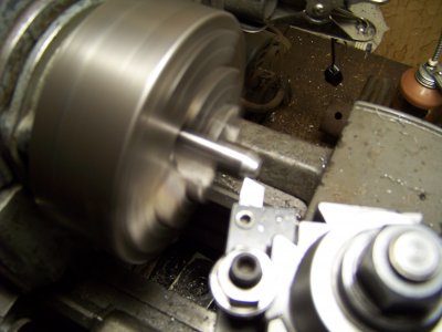
Started with a piece of 5/8" stock, cut to about 1.75" Put it in the lathe, faced off one end, then flipped it over and faced it to length. Next step was to cut the taper on the one end.

100_1133.JPG


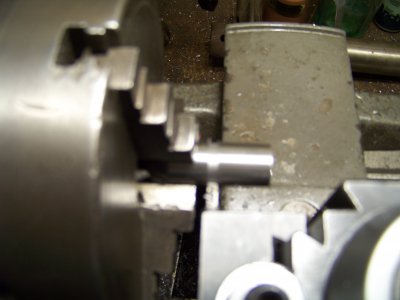
Next, I cut the .155" wide retainer groove using a parting tool. The tool was .125" wide, so two plunge cuts were required, the first being full width, then moving over .030" and taking the second cut. Please excuse the blurriness of a couple of the photos, I got too close for the camera to focus properly but did not realize it.

100_1135.JPG


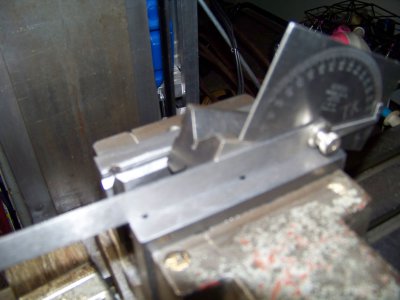
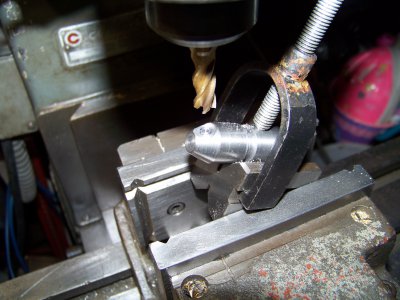
The next step was to spot the tapered end with an end mill. This creates a flat spot that can easily be drilled. The first step in this process was to set a v-block in the mill vice and set it to the correct angle. I could have used a sine bar and gauge blocks to set it perfectly, but this is not that critical and using the protractor was much faster.

100_1137.JPG


Once the v-block was set, the part was clamped in place, and the part was centered under the spindle. This is also a demonstration of why we always use some method other than 'by guess and by gosh' to locate the part in relation to the cutter. You will notice that I did not get the flat spot perfectly centered.

100_1138.JPG


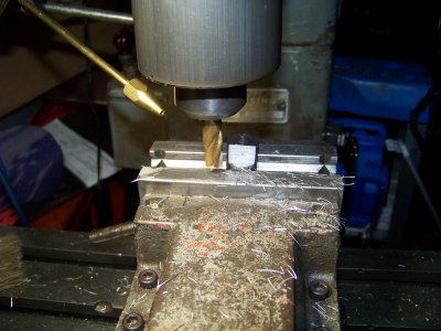
Without changing the setup, a drill chuck replaced the end mill, and the hole was drilled 1/2" deep with a #3 bit, then threaded using a 1/4"-28 tap. The only step after that was to mill the two flats on the end opposite from the taper. The part was mounted in the mill vise using the v-groove jaws, but I could have just as easily used a v-block. I used a temporary handle to properly align the part in the vise so that the flats will be parallel with the handle. Milling the two flats was very straight forward, simply removing .125" of material from each side.

100_1141.JPG


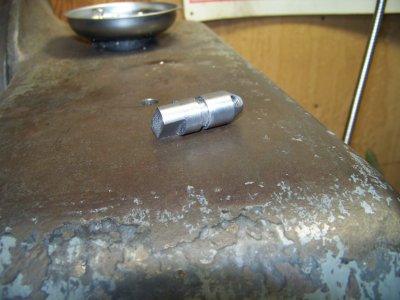
After both flats were milled, the part was removed from the vise and deburred with a file and emery cloth. This completes the cam, leaving only the handle to make.

100_1144.JPG

100_1133.JPG 100_1135.JPG 100_1137.JPG 100_1138.JPG 100_1141.JPG 100_1144.JPG
 
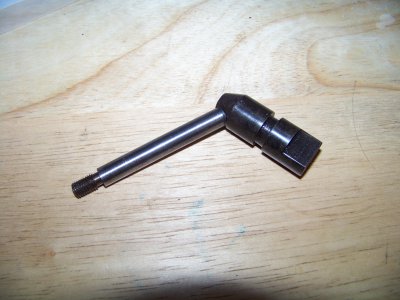
Well, I made the handle and installed it into the cam. The handle is plain old 1018 and the cam is made from W-1 tool steel. I started the wife's oven at 450°F then headed back out to the shop and got out the MAPP torch to heat the part evenly to the point where a magnet would no longer stick to it, then quenched it in water. From there, took it in and put it in the oven for one hour. After it was done with tempering and had cooled, I polished up the handle part, but just oiled up the rest of it. It looks just like the factory brake cam!!

100_1153.JPG


So, it is now in a little plastic bag, waiting to get packaged up and sent out in the mail. I seem to have run out of packing tape, however. Guess I'll have to pick some up!

100_1153.JPG
 
Thanks Again TW! I also learned a few things from this thread. Like the use of the angle block and protractor.. a new "trick" for me!

I'll keep my eyes peeled for the mailman now...:ups:
 
Glad to know that you learned something!! That was the whole reason that I posted the steps that I went through to get it made for you.

On that note, I've been thinking about starting a 'Beginner's Series' of simple projects that those new to the hobby could follow. Users would learn the basics as they go and would make something useful as a result. The series would start with some simple projects like tap holders, machinist clamps, vee blocks, sine bars, etc, and would increase in difficulty as we went. Drawings would be included for each project. I am hoping to get it off the ground this winter. I just need to come up with a difficulty rating system so that each project ends up with a 'difficulty score'. Since nothing can guarantee that I would make the easiest thing first and the hardest thing last, I need to have a way to establish a score for comparison. Gotta give that more thought.

I was out of town for a couple of days, and I finally got it into a Priority Mail box and have it ready to go. It will go out in tomorrow's mail. You should see it early next week.

Time to get out in the garage and get started on the base pin for a Ruger Old Army for a friend.
 
Back
Top