- Joined
- Sep 22, 2010
- Messages
- 7,223
Site is gone, this is from archive.org
Building a Model Steam Engine
I became interested in Home Shop Machining about a year ago when I ran across a website one evening. I haven't been able to find it since but it was one of the things that inspired me to start this page. When I visited homepages and saw really neat miniature steam engines that actually worked I was fascinated. My ultimate goal is to someday build a ¼ scale model of a Ford V-8 engine. I knew that in order to someday do this I would need both the skills and the machines and to that end I've set about acquiring both.
You can look through some of the other pages on my site and you'll see that I've started accumulating the tools and knowledge. Once I had the basic machine tools the next step was to learn how to build working model engines. I'm going to document the steps and the engines that I hope to build. I have 4 sets of castings and plans, including a very nice Stuart that I'll be starting on after I have 2 or 3 other engines under my belt.
I'm always looking for plans for more engines. After I build a few steam engines I plan on trying my hand at Internal Combustion and making some hit & miss engines. I may try a Stirling engine just to have a neat lid for my coffee mug.
This first steam engine that I'm starting is a small vertical oscillating engine. The castings are available through PM research for anyone wanting to build the same. It's an excellent beginners project. The kit comes with all of the castings, a small parts kit that includes the screws but not the steam fittings.
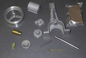
This is what the kit includes. A few of the parts have been started on but very little work has been done at this point. Most kits also include a detailed blueprint that show all parts to be machined and an assembly view such as this.
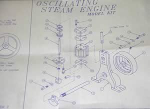
It's up to you to take it from paper to metal.
Shown above are the completed piston rod and the incomplete crankshaft. Below is the partially finished flywheel and piston.
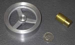
I've spent a lot of time and effort tooling up to make some of these toys that I've been thinking about for so long. Now the shop is pretty close to where I want it and I have all the tooling to start and finish the engine kits that I have now and what I learn building these engines will be needed when I move to Internal Combustion and larger scale models.
I'm going to make more time for my models now. They were the whole reason I started the shop in the first place. The process of buying machine tools and accessories then building all the attachments I couldn't afford to buy was fun and educational but now I want to start devoting more time to the basic reason I started my shop. Every time I build something of my own I regret not being exposed to machine work 20 years ago.
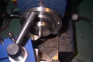
This is the finishing step for the crankshaft; I'm putting a bevel on the ends of the shaft.
The hub of the flywheel has been dyed for marking and a center square is used to find the center.
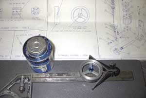
After finding the center the flywheel is secured in a 4" chuck to start the drilling operations. First a center drill is used to locate and start the hole. This is done to keep the long drill bit from "walking" when it tries to start a hole. 3 machinist's squares were used to mount the flywheel squarely on the chuck.
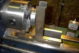
Now we can start.
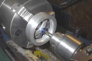
Once the center drill has started the hole the drill bit can be chucked up. Since this was an aluminum flywheel and the center hole wasn't going to be that large I skipped the pilot hole and went directly to the 15/64" bit and started drilling.
And the final step in the process is to ream the hole to its final dimension. A ¼" reamer is being used here to give an accurate and smooth bore for the crankshaft.
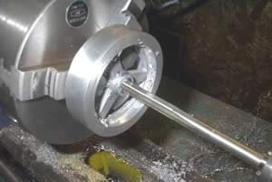
Now to clean up the sides and outer diameter.
A few minutes on the polisher and flywheel, piston rod and crankshaft are complete.
With the first three parts finished it's time to start on the steam chest. Everything in this kit is small enough that a 7" lathe with a 4-jaw chuck is all that would be needed. Having a mini-mill though I just had to use it The top, bottom and back of the chest have to be machined flat.
The castings for this model are aluminum. This is a very easy metal to machine but great care must also be taken not to fracture or break the castings by clamping them to forcefully. I suspect that replacement castings are available at reasonable cost but haven't had to look into it yet. Maybe someone who knows can drop me a note and let me know.
I've been looking at other models and thinking about my own and still haven't decided what color to make it J. Seems kinda trivial I know but hey, there's a lot of work in even the most basic model as I'm hoping to show. I for one want it to look as nice as I hope it will run. While I may not have decided upon a color yet I do know that I'm going to be powder-coating it instead of painting it. After all, why have a powder-coating rig if you're not going to coat everything you can stuff in the oven?
The beauty of learning to do all this on my own is that I get to do everything myway. I've never been to trade school (Ok, I have, but Commercial Diving doesn't apply here) and I've never taken a class on machine work so I'm self-taught from the beginning (and it shows as I am so often reminded) and tend to order my operations in a haphazard way. I've gotten some of the machine work done on the model and I'm satisfied with that for right now. Knowing that I'm going to powder coat the model I'll probably do the pieces in batches as I finish them rather than doing all the machine work and then all of the powder coating. This way I get to see some of the work all colored and shiny and it makes me want to jump back to the machines and finish the next batch of parts. I know, I know, I wouldn't last a week in a production environment but doing it my way seems to keep me more satisfied over the whole length of the project and I find that I'm less apt to lose interest and put it on the shelf for something more interesting.
The castings for this model are aluminum. This is a very easy metal to machine but great care must also be taken not to fracture or break the castings by clamping them to forcefully. I suspect that replacement castings are available at reasonable cost but haven't had to look into it yet. Maybe someone who knows can drop me a note and let me know.
I've been looking at other models and thinking about my own and still haven't decided what color to make it J. Seems kinda trivial I know but hey, there's a lot of work in even the most basic model as I'm hoping to show. I for one want it to look as nice as I hope it will run. While I may not have decided upon a color yet I do know that I'm going to be powder-coating it instead of painting it. After all, why have a powder-coating rig if you're not going to coat everything you can stuff in the oven?
The beauty of learning to do all this on my own is that I get to do everything myway J. I've never been to trade school (Ok, I have, but Commercial Diving doesn't apply here) and I've never taken a class on machine work so I'm self-taught from the beginning (and it shows as I am so often reminded) and tend to order my operations in a haphazard way. I've gotten some of the machine work done on the model and I'm satisfied with that for right now. Knowing that I'm going to powder coat the model I'll probably do the pieces in batches as I finish them rather than doing all the machine work and then all of the powder coating. This way I get to see some of the work all colored and shiny and it makes me want to jump back to the machines and finish the next batch of parts. I know, I know, I wouldn't last a week in a production environment but doing it my way seems to keep me more satisfied over the whole length of the project and I find that I'm less apt to lose interest and put it on the shelf for something more interesting.
Once the cylinder casting is drilled the nest step was to ream it to .50" and give it a smooth bore. After finishing the bore, 4 more holes were drilled through the cylinder casting to secure the caps. This is the bottom cap being reamed to size after drilling.
The cap was clamped to the cylinder to mark the locations of the screw holes.
With the cylinder almost complete I started on the base casting. I had to mill both the top and bottom of the casting to get flat surfaces to work with later. The casting was clamped to an angle plate and then transferred to the mill.
I made light passes with a ¾" 2-flute end-mill and leveled the feet. The casting was then flipped over and the top surface was completed.
Finding the centers for the crankshaft & cylinder pivot turned out to be something of a task. I didn't have an easy way to locate the centers on the casting. Realizing that the "back" of the casting has 3 flat surfaces on the same plane I took the simple shortcut of taping a photocopy of the blueprint to the casting itself to correctly locate the holes.
The photo above shows the working print for the engine, the photocopy that I made and the cutout glued to the casting. I had previously lapped the back of the casting so the surfaces were well suited to this technique.
Once I realized the blueprints were 1-to-1 I figured I could just Cut-and-Paste in a real world sort of way. It seemed silly at first but after thinking it over and trying it out I like the idea. I may try this again on the other models. The next one in line is the PM Research #3A mill engine followed by a Midwest Products oscillator/boiler combo and then my Stuart 10V. What a difference when I look thru the kits, the first three are all similar but the Stuart is in a whole different league, I'm really looking forward to building that one but I realize that I need the practical experience of building the first three to develop my abilities.
I'll say this, machine-work teaches you patience. Unless you have a tremendous natural ability you'll either learn to be patient and take your time or you'll make a whole bunch of scrap. That may not be so bad with designs based on using various stock sizes of material, but when you're working with castings it's a whole different ballgame.
Once the centers were marked on the main casting I clamped it to the small drill press and drilled the undersize holes.
And then the other.
After the holes were drilled and reamed to the correct size I lapped the hole for the crankshaft. I have a small set of laps for just this purpose.
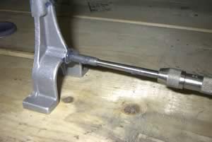
As soon as the mounting holes and steam passages are drilled this casting is finished.
Since this is a learning process I'm trying different techniques as I go along. The original cylinder casting was scrapped when the mill dropped 1/8" while machining and flung it from the vise. Like I said, a learning process J.
I decided to use the lathe when I started in on the replacement cylinder so I'm able to show you the two different ways I machined the same part.
I have to say that using the lathe and 4-jaw was much faster and easier than doing the same job on the mill. Now maybe if my mill were larger, more rigid and dialed in better I would have gotten improved results but as things are and using the machines I have the lathe is the way to go on this one.
I also drilled and reamed the cylinder on the lathe.
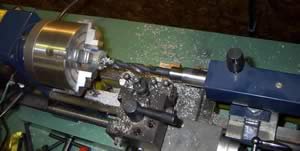
Since the MT2 in the tailstock doesn't use a tang to prevent rotation of the tool there has to be a way to ensure against it. The taper itself is usually sufficient to hold when drilling (aluminum and steel, brass tends to grab the drill bit more often and also requires use of the dog) but I wanted to be sure that the reamer wouldn't spin when I cleaned up the bore so I put a lathe dog on the shaft of the reamer and flipped the toolholder upside down in the toolpost to act as a stop for the dog to rest against. It supported the dog for the entire length of the operation. I was pleased with it and will probably use the dog this way in the future. I had been planning on bolting something to the side of the tailstock to accomplish the same function but this seems to work well and doesn't require any modifications to the machine.
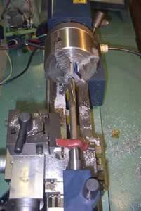
The next step was to drill and tap the eight holes for the screws that hold the cylinder heads on.
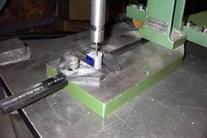
I used the same cut-n-paste for the crank casting.
I'm planning to build the PM Research 3A engine kit next and will explore this technique more fully. I think that paper templates can be used for the main casting, cylinder casting the crank and both cylinder heads. For someone just starting out I think this will be a tremendous help. With most copiers able to scale in either direction it shouldn't be too difficult to produce one-to-one copies of the prints to act as cut-n-paste templates for each workpiece.
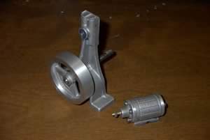
Still plenty of work to do but it's starting to take shape. While I haven't done so yet, it looks like many of the cast pieces could be easily fabricated from aluminum round stock. The whole Idea behind building this engine was for it to be a learning experience, and boy am I learning. Mistakes are easy to make and learning how to fix a mistake is all part of the process. I've picked up a replacement cylinder casting for the original that I scrapped and I also stole the upper cylinder head from the #3A model to use on this one, actually it's a bit nicer with a lathe "PM" cast into it. I'm waiting to see how it runs but I may have to replace the cylinder head yet again. If I do I believe I'll take a shot a just making one from a piece of aluminum round stock.
After being forced to consider ways to replace scrapped castings I started to see how easily an entire engine could be created from bar stock instead of castings. I may alter my intended "build schedule" of steam engines to include one or two scratch-built engines before I tackle the Stuart. The Stuart is the nicest engine I have actual plans to attempt and I'm somewhat intimidated by it. I know I'll feel a great sense of accomplishment when it's done but I want to have a better handle on my skills before I attempt it. This is also based on practicalities. The Stuart is an English casting kit and replacements will be harder to find and more costly than the "cruder" domestic model kits I have at the moment.
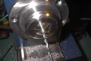
This engine calls for 2 different bushings. One is pressed into the main casting for the cylinder casting to pivot on and the other is pressed into the piston rod connector to allow it to spin on the crankshaft. The "bushing" is just a piece of 3/16" round stock that is drilled out 1/8" on the inside. A collet was the most accurate way to do this. After facing both ends and center-drilling one end I mounted a 1/8" drill bit in the tailstock and drilled out the rod which was later cut into the 2 needed bushings.
Doing the layout work for the model is probably the most important aspect of building it. If you don't get your layout right then forget it, nothing will be the right size and holes will be misaligned. There are a lot of different ways to lay out your work; I'll try to show you some of the ideas I used.
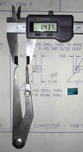
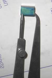
The connector above attached the piston rod to the crankshaft and according to the print it needs to be 7/16" long. To get the right length I used the decimal equivalent and set the digital calipers to .4375". Once the calipers were set and locked I transferred the measurement to a set of hermaphrodite calipers and then transferred the measurement to the brass key stock, which has been dyed with blue layout fluid. Once the proper length is determined and marked, the connector is placed in a square hole collet and turned on the lathe. A 4-jaw chuck would usually be use but since this is such a small piece that the collet is a better choice when one is available. This is exactly the kind of operation that I was thinking of when I set out to equip my 7" lathes with a 3C collet closer. Pictures and details of the closer can be found elsewhere on this site.
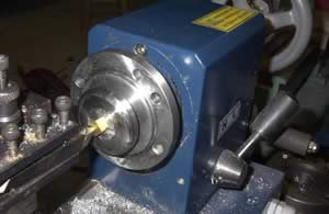
Now that it's the right size the real work can begin. Once again I used a paper template made from the prints.
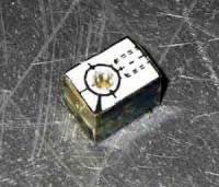
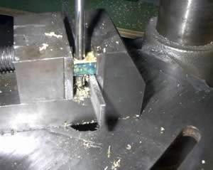
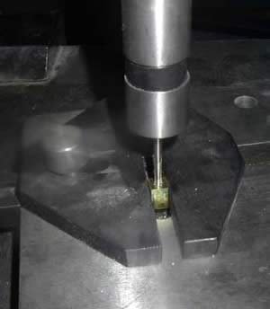
The bushing hole was center drilled, drilled and then reamed on the drill press and then it was back to the lathe to mark and drill the hole to be tapped for the piston rod.
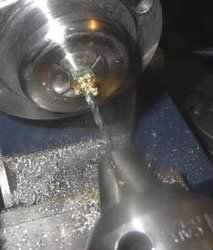
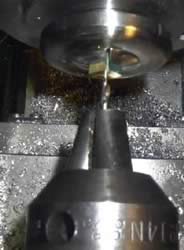
The connector now needs to have the hole for the piston rod threaded and the bushing pressed in.
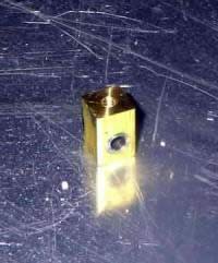
And presto, one completed piston rod connector. It can be surprising just how much work goes into making just one part of this engine. Fortunately there aren't too many pieces to this engine, which is what makes it such a good beginners project.
I didn't stumble upon this method of laying out my work until I was about ½ way finished, but I plan to make more use of it in the future. With most copiers able to scale the copy either up or down it should be easy to obtain the size print that you need for the part. Paper templates have been very useful in this project.
As I do more and more work I'm sure my layout skills will increase and at some point using templates such as this won't be necessary but for now while I still have so much to learn I find that they save me a great deal of time, aggravation and disappointment.
With the bushings and connector finished the list of unfinished parts grows smaller each day. I only have the steam passages to drill and the piston to make and all of the machine-work is finished. The next step when the parts are all finished will be to individually clean and inspect all of the parts a final time. The engine will be assembled to test fit everything and to identify any problems. With everything assembled I'll put some compressed air to the engine to get it chugging along. When everything is together and working smoothly I'll take it apart one final time to polish all of the brass parts and powder-coat the rest. I won't do any of the polishing or coating until I know that the engine runs and won't need to be taken apart again.
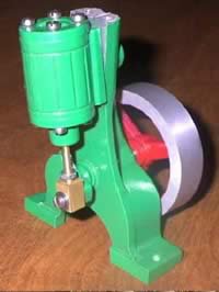
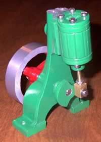
Almost there, this is how it's looking so far.
I still have a few things to do and last minute modifications. Since this is just going to be a display engine and won't be powering anything I don't need the extended crankshaft. Before the final assembly I will shorten the shaft to make for a cleaner appearance. I still haven't decided what colors to finish it in. I have a small variety of powders and don't know yet what will look best. Something colorful perhaps. I an engine turned finish on a scrap of brass and think it would be a great look for the sides of the flywheel but I need more practice applying the finish before I try it on a model. Maybe when I build the 3A or another 2A like this. I also need to start thinking about how I want to display it. I'd like to build a boiler to run it from for the best effect. While compressed air is simple there's just something about running one of these on steam.
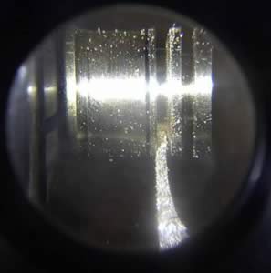
Here's a picture of the first piston that I started. It remains unfinished although it may be salvageable. This first attempt has as usual, taught me a few things. The first is that I nee a netter tool for cutting the grooves the piston rings will sit in. I originally used a modified cut-off blade but as you can see it tapered to a point. This made it impossible to get the side profile of the groove correct. A quick construction note here, I did all the work on this piston looking through a 10x jeweler's loupe. Watching what was happening so closely and clearly was very educational and showed that I would have to make a better tool in order to make a better cut.
After making the initial cuts I had to grind a second tool to try and square the sides of the V-grooves that I had just cut. I was able to square everything on the top groove but I'm afraid that the ring is going to sit too low and I stopped before finishing the second groove to reconsider everything. I don't want to waste any further time on a scrapped part but would also rather salvage this ten start from scratch. Since the piston itself is only .25" I think I have enough left on the machines stub to make a second without having to make any more cuts, I could just part off this piston and start again. I'm not sure yet, have to see how well the existing piston & ring fit the bore.
Finished
Building a Model Steam Engine
I became interested in Home Shop Machining about a year ago when I ran across a website one evening. I haven't been able to find it since but it was one of the things that inspired me to start this page. When I visited homepages and saw really neat miniature steam engines that actually worked I was fascinated. My ultimate goal is to someday build a ¼ scale model of a Ford V-8 engine. I knew that in order to someday do this I would need both the skills and the machines and to that end I've set about acquiring both.
You can look through some of the other pages on my site and you'll see that I've started accumulating the tools and knowledge. Once I had the basic machine tools the next step was to learn how to build working model engines. I'm going to document the steps and the engines that I hope to build. I have 4 sets of castings and plans, including a very nice Stuart that I'll be starting on after I have 2 or 3 other engines under my belt.
I'm always looking for plans for more engines. After I build a few steam engines I plan on trying my hand at Internal Combustion and making some hit & miss engines. I may try a Stirling engine just to have a neat lid for my coffee mug.
This first steam engine that I'm starting is a small vertical oscillating engine. The castings are available through PM research for anyone wanting to build the same. It's an excellent beginners project. The kit comes with all of the castings, a small parts kit that includes the screws but not the steam fittings.

This is what the kit includes. A few of the parts have been started on but very little work has been done at this point. Most kits also include a detailed blueprint that show all parts to be machined and an assembly view such as this.

It's up to you to take it from paper to metal.
Shown above are the completed piston rod and the incomplete crankshaft. Below is the partially finished flywheel and piston.

I've spent a lot of time and effort tooling up to make some of these toys that I've been thinking about for so long. Now the shop is pretty close to where I want it and I have all the tooling to start and finish the engine kits that I have now and what I learn building these engines will be needed when I move to Internal Combustion and larger scale models.
I'm going to make more time for my models now. They were the whole reason I started the shop in the first place. The process of buying machine tools and accessories then building all the attachments I couldn't afford to buy was fun and educational but now I want to start devoting more time to the basic reason I started my shop. Every time I build something of my own I regret not being exposed to machine work 20 years ago.
This is the finishing step for the crankshaft; I'm putting a bevel on the ends of the shaft.

The hub of the flywheel has been dyed for marking and a center square is used to find the center.

After finding the center the flywheel is secured in a 4" chuck to start the drilling operations. First a center drill is used to locate and start the hole. This is done to keep the long drill bit from "walking" when it tries to start a hole. 3 machinist's squares were used to mount the flywheel squarely on the chuck.

Now we can start.

Once the center drill has started the hole the drill bit can be chucked up. Since this was an aluminum flywheel and the center hole wasn't going to be that large I skipped the pilot hole and went directly to the 15/64" bit and started drilling.
And the final step in the process is to ream the hole to its final dimension. A ¼" reamer is being used here to give an accurate and smooth bore for the crankshaft.

Now to clean up the sides and outer diameter.
A few minutes on the polisher and flywheel, piston rod and crankshaft are complete.
With the first three parts finished it's time to start on the steam chest. Everything in this kit is small enough that a 7" lathe with a 4-jaw chuck is all that would be needed. Having a mini-mill though I just had to use it
The castings for this model are aluminum. This is a very easy metal to machine but great care must also be taken not to fracture or break the castings by clamping them to forcefully. I suspect that replacement castings are available at reasonable cost but haven't had to look into it yet. Maybe someone who knows can drop me a note and let me know.
I've been looking at other models and thinking about my own and still haven't decided what color to make it J. Seems kinda trivial I know but hey, there's a lot of work in even the most basic model as I'm hoping to show. I for one want it to look as nice as I hope it will run. While I may not have decided upon a color yet I do know that I'm going to be powder-coating it instead of painting it. After all, why have a powder-coating rig if you're not going to coat everything you can stuff in the oven?
The beauty of learning to do all this on my own is that I get to do everything myway. I've never been to trade school (Ok, I have, but Commercial Diving doesn't apply here) and I've never taken a class on machine work so I'm self-taught from the beginning (and it shows as I am so often reminded) and tend to order my operations in a haphazard way. I've gotten some of the machine work done on the model and I'm satisfied with that for right now. Knowing that I'm going to powder coat the model I'll probably do the pieces in batches as I finish them rather than doing all the machine work and then all of the powder coating. This way I get to see some of the work all colored and shiny and it makes me want to jump back to the machines and finish the next batch of parts. I know, I know, I wouldn't last a week in a production environment but doing it my way seems to keep me more satisfied over the whole length of the project and I find that I'm less apt to lose interest and put it on the shelf for something more interesting.
The castings for this model are aluminum. This is a very easy metal to machine but great care must also be taken not to fracture or break the castings by clamping them to forcefully. I suspect that replacement castings are available at reasonable cost but haven't had to look into it yet. Maybe someone who knows can drop me a note and let me know.
I've been looking at other models and thinking about my own and still haven't decided what color to make it J. Seems kinda trivial I know but hey, there's a lot of work in even the most basic model as I'm hoping to show. I for one want it to look as nice as I hope it will run. While I may not have decided upon a color yet I do know that I'm going to be powder-coating it instead of painting it. After all, why have a powder-coating rig if you're not going to coat everything you can stuff in the oven?
The beauty of learning to do all this on my own is that I get to do everything myway J. I've never been to trade school (Ok, I have, but Commercial Diving doesn't apply here) and I've never taken a class on machine work so I'm self-taught from the beginning (and it shows as I am so often reminded) and tend to order my operations in a haphazard way. I've gotten some of the machine work done on the model and I'm satisfied with that for right now. Knowing that I'm going to powder coat the model I'll probably do the pieces in batches as I finish them rather than doing all the machine work and then all of the powder coating. This way I get to see some of the work all colored and shiny and it makes me want to jump back to the machines and finish the next batch of parts. I know, I know, I wouldn't last a week in a production environment but doing it my way seems to keep me more satisfied over the whole length of the project and I find that I'm less apt to lose interest and put it on the shelf for something more interesting.
Once the cylinder casting is drilled the nest step was to ream it to .50" and give it a smooth bore. After finishing the bore, 4 more holes were drilled through the cylinder casting to secure the caps. This is the bottom cap being reamed to size after drilling.
The cap was clamped to the cylinder to mark the locations of the screw holes.
With the cylinder almost complete I started on the base casting. I had to mill both the top and bottom of the casting to get flat surfaces to work with later. The casting was clamped to an angle plate and then transferred to the mill.
I made light passes with a ¾" 2-flute end-mill and leveled the feet. The casting was then flipped over and the top surface was completed.
Finding the centers for the crankshaft & cylinder pivot turned out to be something of a task. I didn't have an easy way to locate the centers on the casting. Realizing that the "back" of the casting has 3 flat surfaces on the same plane I took the simple shortcut of taping a photocopy of the blueprint to the casting itself to correctly locate the holes.
The photo above shows the working print for the engine, the photocopy that I made and the cutout glued to the casting. I had previously lapped the back of the casting so the surfaces were well suited to this technique.
Once I realized the blueprints were 1-to-1 I figured I could just Cut-and-Paste in a real world sort of way. It seemed silly at first but after thinking it over and trying it out I like the idea. I may try this again on the other models. The next one in line is the PM Research #3A mill engine followed by a Midwest Products oscillator/boiler combo and then my Stuart 10V. What a difference when I look thru the kits, the first three are all similar but the Stuart is in a whole different league, I'm really looking forward to building that one but I realize that I need the practical experience of building the first three to develop my abilities.
I'll say this, machine-work teaches you patience. Unless you have a tremendous natural ability you'll either learn to be patient and take your time or you'll make a whole bunch of scrap. That may not be so bad with designs based on using various stock sizes of material, but when you're working with castings it's a whole different ballgame.
Once the centers were marked on the main casting I clamped it to the small drill press and drilled the undersize holes.
And then the other.
After the holes were drilled and reamed to the correct size I lapped the hole for the crankshaft. I have a small set of laps for just this purpose.

As soon as the mounting holes and steam passages are drilled this casting is finished.
Since this is a learning process I'm trying different techniques as I go along. The original cylinder casting was scrapped when the mill dropped 1/8" while machining and flung it from the vise. Like I said, a learning process J.
I decided to use the lathe when I started in on the replacement cylinder so I'm able to show you the two different ways I machined the same part.
I have to say that using the lathe and 4-jaw was much faster and easier than doing the same job on the mill. Now maybe if my mill were larger, more rigid and dialed in better I would have gotten improved results but as things are and using the machines I have the lathe is the way to go on this one.
I also drilled and reamed the cylinder on the lathe.

Since the MT2 in the tailstock doesn't use a tang to prevent rotation of the tool there has to be a way to ensure against it. The taper itself is usually sufficient to hold when drilling (aluminum and steel, brass tends to grab the drill bit more often and also requires use of the dog) but I wanted to be sure that the reamer wouldn't spin when I cleaned up the bore so I put a lathe dog on the shaft of the reamer and flipped the toolholder upside down in the toolpost to act as a stop for the dog to rest against. It supported the dog for the entire length of the operation. I was pleased with it and will probably use the dog this way in the future. I had been planning on bolting something to the side of the tailstock to accomplish the same function but this seems to work well and doesn't require any modifications to the machine.

The next step was to drill and tap the eight holes for the screws that hold the cylinder heads on.

I used the same cut-n-paste for the crank casting.

I'm planning to build the PM Research 3A engine kit next and will explore this technique more fully. I think that paper templates can be used for the main casting, cylinder casting the crank and both cylinder heads. For someone just starting out I think this will be a tremendous help. With most copiers able to scale in either direction it shouldn't be too difficult to produce one-to-one copies of the prints to act as cut-n-paste templates for each workpiece.

Still plenty of work to do but it's starting to take shape. While I haven't done so yet, it looks like many of the cast pieces could be easily fabricated from aluminum round stock. The whole Idea behind building this engine was for it to be a learning experience, and boy am I learning. Mistakes are easy to make and learning how to fix a mistake is all part of the process. I've picked up a replacement cylinder casting for the original that I scrapped and I also stole the upper cylinder head from the #3A model to use on this one, actually it's a bit nicer with a lathe "PM" cast into it. I'm waiting to see how it runs but I may have to replace the cylinder head yet again. If I do I believe I'll take a shot a just making one from a piece of aluminum round stock.
After being forced to consider ways to replace scrapped castings I started to see how easily an entire engine could be created from bar stock instead of castings. I may alter my intended "build schedule" of steam engines to include one or two scratch-built engines before I tackle the Stuart. The Stuart is the nicest engine I have actual plans to attempt and I'm somewhat intimidated by it. I know I'll feel a great sense of accomplishment when it's done but I want to have a better handle on my skills before I attempt it. This is also based on practicalities. The Stuart is an English casting kit and replacements will be harder to find and more costly than the "cruder" domestic model kits I have at the moment.

This engine calls for 2 different bushings. One is pressed into the main casting for the cylinder casting to pivot on and the other is pressed into the piston rod connector to allow it to spin on the crankshaft. The "bushing" is just a piece of 3/16" round stock that is drilled out 1/8" on the inside. A collet was the most accurate way to do this. After facing both ends and center-drilling one end I mounted a 1/8" drill bit in the tailstock and drilled out the rod which was later cut into the 2 needed bushings.
Doing the layout work for the model is probably the most important aspect of building it. If you don't get your layout right then forget it, nothing will be the right size and holes will be misaligned. There are a lot of different ways to lay out your work; I'll try to show you some of the ideas I used.


The connector above attached the piston rod to the crankshaft and according to the print it needs to be 7/16" long. To get the right length I used the decimal equivalent and set the digital calipers to .4375". Once the calipers were set and locked I transferred the measurement to a set of hermaphrodite calipers and then transferred the measurement to the brass key stock, which has been dyed with blue layout fluid. Once the proper length is determined and marked, the connector is placed in a square hole collet and turned on the lathe. A 4-jaw chuck would usually be use but since this is such a small piece that the collet is a better choice when one is available. This is exactly the kind of operation that I was thinking of when I set out to equip my 7" lathes with a 3C collet closer. Pictures and details of the closer can be found elsewhere on this site.

Now that it's the right size the real work can begin. Once again I used a paper template made from the prints.


The bushing hole was center drilled, drilled and then reamed on the drill press and then it was back to the lathe to mark and drill the hole to be tapped for the piston rod.


The connector now needs to have the hole for the piston rod threaded and the bushing pressed in.


And presto, one completed piston rod connector. It can be surprising just how much work goes into making just one part of this engine. Fortunately there aren't too many pieces to this engine, which is what makes it such a good beginners project.
I didn't stumble upon this method of laying out my work until I was about ½ way finished, but I plan to make more use of it in the future. With most copiers able to scale the copy either up or down it should be easy to obtain the size print that you need for the part. Paper templates have been very useful in this project.
As I do more and more work I'm sure my layout skills will increase and at some point using templates such as this won't be necessary but for now while I still have so much to learn I find that they save me a great deal of time, aggravation and disappointment.
With the bushings and connector finished the list of unfinished parts grows smaller each day. I only have the steam passages to drill and the piston to make and all of the machine-work is finished. The next step when the parts are all finished will be to individually clean and inspect all of the parts a final time. The engine will be assembled to test fit everything and to identify any problems. With everything assembled I'll put some compressed air to the engine to get it chugging along. When everything is together and working smoothly I'll take it apart one final time to polish all of the brass parts and powder-coat the rest. I won't do any of the polishing or coating until I know that the engine runs and won't need to be taken apart again.
Almost there, this is how it's looking so far.
I still have a few things to do and last minute modifications. Since this is just going to be a display engine and won't be powering anything I don't need the extended crankshaft. Before the final assembly I will shorten the shaft to make for a cleaner appearance. I still haven't decided what colors to finish it in. I have a small variety of powders and don't know yet what will look best. Something colorful perhaps. I an engine turned finish on a scrap of brass and think it would be a great look for the sides of the flywheel but I need more practice applying the finish before I try it on a model. Maybe when I build the 3A or another 2A like this. I also need to start thinking about how I want to display it. I'd like to build a boiler to run it from for the best effect. While compressed air is simple there's just something about running one of these on steam.
Here's a picture of the first piston that I started. It remains unfinished although it may be salvageable. This first attempt has as usual, taught me a few things. The first is that I nee a netter tool for cutting the grooves the piston rings will sit in. I originally used a modified cut-off blade but as you can see it tapered to a point. This made it impossible to get the side profile of the groove correct. A quick construction note here, I did all the work on this piston looking through a 10x jeweler's loupe. Watching what was happening so closely and clearly was very educational and showed that I would have to make a better tool in order to make a better cut.
After making the initial cuts I had to grind a second tool to try and square the sides of the V-grooves that I had just cut. I was able to square everything on the top groove but I'm afraid that the ring is going to sit too low and I stopped before finishing the second groove to reconsider everything. I don't want to waste any further time on a scrapped part but would also rather salvage this ten start from scratch. Since the piston itself is only .25" I think I have enough left on the machines stub to make a second without having to make any more cuts, I could just part off this piston and start again. I'm not sure yet, have to see how well the existing piston & ring fit the bore.

Finished


Last edited by a moderator:

