- Joined
- Feb 5, 2015
- Messages
- 662
<!--[if gte mso 9]><xml> <w:WordDocument> <w:View>Normal</w:View> <w:Zoom>0</w:Zoom> <w unctuationKerning/> <w:ValidateAgainstSchemas/> <w:SaveIfXMLInvalid>false</w:SaveIfXMLInvalid> <w:IgnoreMixedContent>false</w:IgnoreMixedContent> <w:AlwaysShowPlaceholderText>false</w:AlwaysShowPlaceholderText> <w:Compatibility> <w:BreakWrappedTables/> <w:SnapToGridInCell/> <w:WrapTextWithPunct/> <w:UseAsianBreakRules/> <w
 ontGrowAutofit/> </w:Compatibility> <w:BrowserLevel>MicrosoftInternetExplorer4</w:BrowserLevel> </w:WordDocument> </xml><![endif]-->Expediency is often the motivation for devising a new tool or a new method of performing a task. The following doesn't purport to be much of anything special, just a quick fix to a problem that ended up being useful for other purposes. As the title suggests, an inexpensive trim router was attached to the quill of a vertical mill by means of an adaptor.
If I had this to do over again, I'd use a small air-powered die-grinder rather than a trim router and I would use heavy aluminum jig-plate to mount the die-grinder to the quill. This would be a far more rigid configuration than the typical plastic housing of small trim routers while retaining the popular 1/4 collet toolholder. OK, here's the original story:
A few years ago, I broke a small No. 4-40 tap in a piece that was 99% complete. There was no time to re-make the part and no way for me to remove the tap except possibly by disintegrating it with a solid carbide end mill. I happened to have several 5/64 solid carbide mills (used for routing printed wiring boards, I think) so I installed one in the milling machine being careful to leave the dials untouched so that the registration would be good (I had been tapping in the mill in the same setup as drilling the pilot hole).
The fastest speed my mill is capable is 3200 RPM so I adjusted the belts for that speed and carefully lowered the spindle to the broken tap. "Ping" - the end mill popped the instant that it touched the broken tap. I had two more tries (the number of remaining 5/64 end mills) to get it right. I knew that the spindle speed wasn't nearly high enough for the tiny carbide tools and thought that the slightest spindle movement might deflect the end mill enough to snap it.
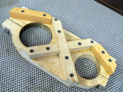
In other words, I reasoned that the problem wasn't just the speed but perhaps more of a feed problem as well - I was limited as to how fine I could feed the tool by the vertical boring handwheel gearing on the vertical mill. I drove into town and bought two cheap Chinese trim routers (less than $20 each at the time). I didn't have much confidence in my idea (and I was rushed) so I didn't want to spend the time to machine or weld anything; I made the following fixture out of scrap pieces of oak using five-minute epoxy and deck screws:
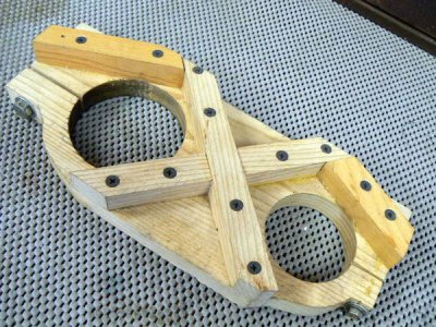
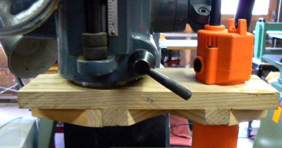
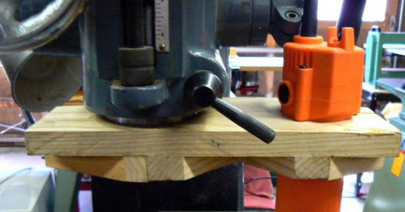
Luckily the carbide end mills had 1/4 shanks, the size of the trim router collets. The router fits into one of the two split-ring holes in the oak fixture and is clamped tightly using a screw to "squeeze" the split ring together. The other hole in the fixture slides over the quill and is also clamped tightly by the split ring. I didn't make any photos of the original setup and procedure but here's a photo of the trim router mounted to the quill of the vertical mill:
I had lost my X-Y reference because of the offset of the trim router from the quill so I had to set up a microscope on the mill table and monkey around with the X, Y handwheels until the carbide end mill was again centered on the broken tap. I turned on the router motor and cranked the boring handwheel downward as carefully as I could. Saw a few sparks but nothing sounded (or felt) wrong so I kept feeding very slowly until I knew that I was past the broken tap. Slowly backing out of the hole I saw - to my profound relief - that the carbide mill was unbroken.
Using a hardened scribe under the microscope, I was able to chip and pick away at the pieces of broken tap until the hole was clear. I CAREFULLY completed the tapping and sent the part on its way that afternoon. I was very, very lucky and I haven't tried that trick again !
I was satisfied with the way that the "temporary" wooden fixture had worked in this emergency situation. I thought to myself that one day I'd make a better one from aluminum jig plate - it was so handy to be able to have the high speed capability occasionally. Needless to say, I never got around to making a more substantial fixture but stored the oak one underneath the workbench and forgot about it. Until the next time I needed a high speed spindle.
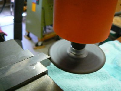
Used the fixture again not long ago to make a forming tool out of a 1/2 square HSS tool bit. Here's a photo of the trim router with a 3 inch abrasive slitting wheel installed on a home-made arbor:
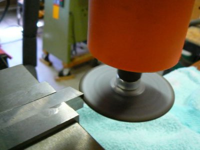
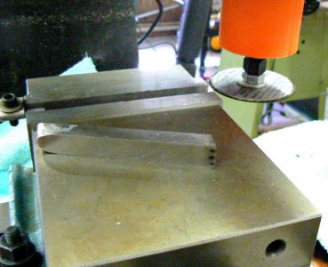
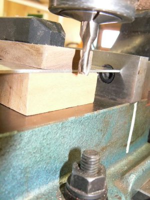
The mill table and vertical ways are covered with towels, the HSS tool bit is clamped in the milling vise and I am feeding the trim router slowly with the "Y" handwheel. I need to make three plunges at several depths in the tool bit after which I will worry the slots into the proper (side relief) configuration by hand with diamond files. Here's the roughed-out tool bit after making the first slotting passes with the trim router:
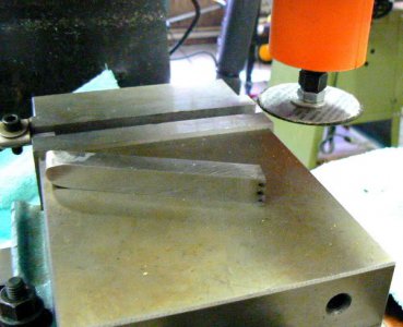
This took about five minutes but would have taken several hours if I'd had to make those slots by hand (diamond blade in a jeweler's saw). Still needs a lot of hand cleanup work before it's ready for use.
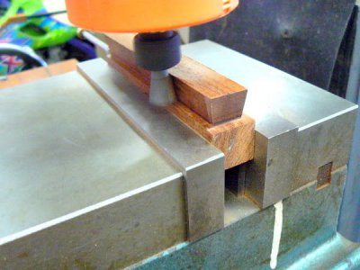
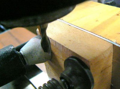
Another fine application for the little trim router on the milling machine is routing wood parts that are too small to safely produce with a manual table router. Here's an example of a small block of "cocobola" that is to be used as a drawer pull. I've had poor results gluing this wood using my normal practice so, for strength, it will be inserted into a dovetail. I'm making the dovetail in the pull with the part clamped in my milling vise.
After the drawer pulls are completed and installed on each side of the drawer, the same setup will be used to produce two "keys". The keys will be made of the same wood as the front of the drawer and will be inserted and glued into place to hide the dovetails routed into the drawer front for the pulls.
After the glue has cured, the tops of the keys will be cut/sanded flush to the drawer front. It is a simple matter to produce parts with tolerances of a few thousands of an inch so the keys should be invisible after applying finish to the drawer front. (UNLESS the keys have been made from wood with a different grain or coloration as the drawer front.)
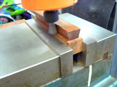
Making this part on a router table may have been a recipe for disaster - it's certain that I would have scrapped one part for every two good ones, not to mention the workpiece flying through the shop in the event of a kickback (the very narrow part would be hard to hold flat on the router table). With the work secured in the mill vise, there was minimal possibility of an accident, even when climb cutting which produces the nicest finish.
When working wood on any metalworking machinery, it's best to use a shop vacuum to collect the chips during the cutting process. Place the hose as close to the cutting tool as can be safely done. Not only does it avoid time-consuming clean up but is WAY better for your lungs. The same advice applies if one has to perform a grinding operation on lathe or mill - get the shop vac pickup as close to the wheel as you can safely get it and cover all exposed surfaces. Make sure that the covering cannot be accidentally picked up (in a lead screw, for example, or a crank and DEFINITELY not by the cutting tool, LOL).
And now some notes on SAFETY and common sense -
Temporary protective shielding was placed on the mill table during the grinding operation. I stacked several short lengths of 4 x 4 timbers on the table, between me and the abrasive wheel, except to take the photos, for protection.
I don't advocate the use of wooden tooling as a rule although there are times when it can be very helpful. The forces and loads normally encountered in machining operations can cause even sturdy wooden structures to deflect. The purpose of the previous post was to point out that there are alternative means of accomplishing some tasks when the nature of the task requires only small applications of force.
But NEVER let expediency take the place of SAFETY !
The previous examples are indicative of operations where very little feed pressure is required and when higher speed minimizes the risk associated with the operation or improves performance. To more clearly visualize how higher speed reduces the chance of too much feed, imagine a large panel router cutter operating at 100 RPM rather than at 5,000 RPM. The chances of kickback would be immense because the feed would be so difficult to control manually. High speed allows low chip loading and more controllable feed in most situations (provided that the cutter is operated within its "SFPM" limits).
Here's a mental trick that I've used for a long time when evaluating the safety of a machine setup. I visualize the cutting tool as a chisel and then imagine the chisel being struck by a hammer with the chisel point applied to the flimsiest part - or direction - of the workpiece in the setup. If my mental picture "sees" the chisel strike the workpiece and my brain processes the information and returns the answer "it's rigid enough" then a first test has been passed.
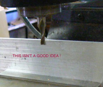
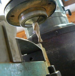
Let's create an example. Suppose one needs to cut a 0.25 x 0.25 notch in the edge of a piece of aluminum that is 6 x 4 inches and .035 thick. An immediate instinct - if inexperienced - might be to place the sheet vertically, clamped in the mill vise and run a 0.25 diameter cutter through the top of the sheet to create the notch. Applying the mental "test", imagine that the cutter is a chisel … then imagine placing the point of the chisel at the top of the aluminum sheet and tapping it with a hammer.
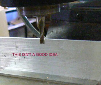
Clearly, the aluminum will not be readily cut, it will be deflected away from the pressure of the cutting tool - the setup is obviously not very rigid and therefore not a good one. Now imagine placing the aluminum horizontally in the mill vise (assuming the vise will open to that extent), visualize placing a chisel on the edge of the sheet and tapping it with a hammer.
Your brain might process the problem and send two alternate signals, in one the chisel meets resistance and can cut the edge of the sheet. But in the other scenario, the clamping pressure of the vise causes the sheet to bend (it has "buckled" and any further pressure simply bends the sheet further). Placing a chisel against the edge of the sheet and tapping it will cause the sheet to slip in the vise as a consequence of the application of the force, rather than being cut. This is also obviously undesirable.
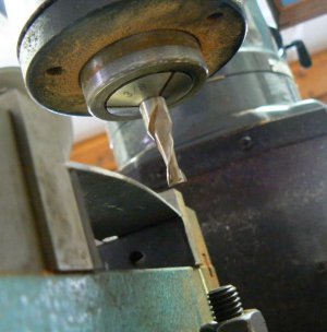
Common sense is invaluable when making a machine setup. There are a number of ways to clamp the aluminum sheet in the above example so that it can be safely machined but there aren't any QUICK ways to do so with "normal" machinery and tooling available to the "normal" home machinist. How one sets up this particular task requires evaluating the variables, the resources on hand and the safety of the resulting process.
It might be convenient, for example, to sandwich the aluminum part between two scrap hardwood blocks, everything clamped in the milling vise and maybe adding a couple of "C" clamps near the top of the structure. The wooden blocks will support the thin aluminum sheet while also dampening vibration from the cutting process - just mill right through the wood and through the aluminum.
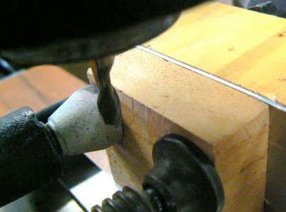
Another option would be to use a couple of step blocks and clamp the sheet horizontally directly to the mill table using strap clamps. It may still be useful to employ a couple of scraps of wood to sandwich the aluminum where the notch was to be cut. Or perhaps a compromise setup, using both milling vise and strap clamp ...
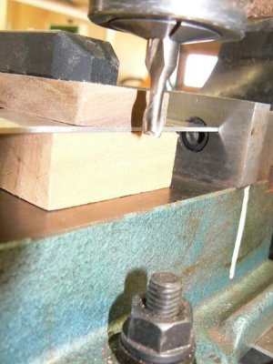
But if you spent more than five minutes worrying about this setup, you could have already cut the notch with a jeweler's saw or a bandsaw and filed the edges clean and straight. There's not a single thing wrong with using hand tools - frequently this is a better alternative than using a machine tool just "because it is there". We know that the first machine tools were built with hand tools - the accuracy is in the craftsman, not the tool.
One more point: if there's any doubt about the rigidity of a setup, it's not a bad idea to use a soft-face hammer to "evaluate" the setup for weaknesses - a few sharp taps at questionable areas to verify that nothing slips can go a long way toward establishing confidence in the setup and the machining process before touching the "on" switch, LOL.
<!--[if gte mso 9]><xml> <w:LatentStyles DefLockedState="false" LatentStyleCount="156"> </w:LatentStyles> </xml><![endif]--><!--[if gte mso 10]> <style> /* Style Definitions */ table.MsoNormalTable {mso-style-name:"Table Normal"; mso-tstyle-rowband-size:0; mso-tstyle-colband-size:0; mso-style-noshow:yes; mso-style-parent:""; mso-padding-alt:0in 5.4pt 0in 5.4pt; mso-para-margin:0in; mso-para-margin-bottom:.0001pt; mso-pagination:widow-orphan; font-size:10.0pt; font-family:"Times New Roman"; mso-ansi-language:#0400; mso-fareast-language:#0400; mso-bidi-language:#0400;} </style> <![endif]-->
If I had this to do over again, I'd use a small air-powered die-grinder rather than a trim router and I would use heavy aluminum jig-plate to mount the die-grinder to the quill. This would be a far more rigid configuration than the typical plastic housing of small trim routers while retaining the popular 1/4 collet toolholder. OK, here's the original story:
A few years ago, I broke a small No. 4-40 tap in a piece that was 99% complete. There was no time to re-make the part and no way for me to remove the tap except possibly by disintegrating it with a solid carbide end mill. I happened to have several 5/64 solid carbide mills (used for routing printed wiring boards, I think) so I installed one in the milling machine being careful to leave the dials untouched so that the registration would be good (I had been tapping in the mill in the same setup as drilling the pilot hole).
The fastest speed my mill is capable is 3200 RPM so I adjusted the belts for that speed and carefully lowered the spindle to the broken tap. "Ping" - the end mill popped the instant that it touched the broken tap. I had two more tries (the number of remaining 5/64 end mills) to get it right. I knew that the spindle speed wasn't nearly high enough for the tiny carbide tools and thought that the slightest spindle movement might deflect the end mill enough to snap it.
In other words, I reasoned that the problem wasn't just the speed but perhaps more of a feed problem as well - I was limited as to how fine I could feed the tool by the vertical boring handwheel gearing on the vertical mill. I drove into town and bought two cheap Chinese trim routers (less than $20 each at the time). I didn't have much confidence in my idea (and I was rushed) so I didn't want to spend the time to machine or weld anything; I made the following fixture out of scrap pieces of oak using five-minute epoxy and deck screws:

Luckily the carbide end mills had 1/4 shanks, the size of the trim router collets. The router fits into one of the two split-ring holes in the oak fixture and is clamped tightly using a screw to "squeeze" the split ring together. The other hole in the fixture slides over the quill and is also clamped tightly by the split ring. I didn't make any photos of the original setup and procedure but here's a photo of the trim router mounted to the quill of the vertical mill:

I had lost my X-Y reference because of the offset of the trim router from the quill so I had to set up a microscope on the mill table and monkey around with the X, Y handwheels until the carbide end mill was again centered on the broken tap. I turned on the router motor and cranked the boring handwheel downward as carefully as I could. Saw a few sparks but nothing sounded (or felt) wrong so I kept feeding very slowly until I knew that I was past the broken tap. Slowly backing out of the hole I saw - to my profound relief - that the carbide mill was unbroken.
Using a hardened scribe under the microscope, I was able to chip and pick away at the pieces of broken tap until the hole was clear. I CAREFULLY completed the tapping and sent the part on its way that afternoon. I was very, very lucky and I haven't tried that trick again !
I was satisfied with the way that the "temporary" wooden fixture had worked in this emergency situation. I thought to myself that one day I'd make a better one from aluminum jig plate - it was so handy to be able to have the high speed capability occasionally. Needless to say, I never got around to making a more substantial fixture but stored the oak one underneath the workbench and forgot about it. Until the next time I needed a high speed spindle.
Used the fixture again not long ago to make a forming tool out of a 1/2 square HSS tool bit. Here's a photo of the trim router with a 3 inch abrasive slitting wheel installed on a home-made arbor:

The mill table and vertical ways are covered with towels, the HSS tool bit is clamped in the milling vise and I am feeding the trim router slowly with the "Y" handwheel. I need to make three plunges at several depths in the tool bit after which I will worry the slots into the proper (side relief) configuration by hand with diamond files. Here's the roughed-out tool bit after making the first slotting passes with the trim router:

This took about five minutes but would have taken several hours if I'd had to make those slots by hand (diamond blade in a jeweler's saw). Still needs a lot of hand cleanup work before it's ready for use.
Another fine application for the little trim router on the milling machine is routing wood parts that are too small to safely produce with a manual table router. Here's an example of a small block of "cocobola" that is to be used as a drawer pull. I've had poor results gluing this wood using my normal practice so, for strength, it will be inserted into a dovetail. I'm making the dovetail in the pull with the part clamped in my milling vise.
After the drawer pulls are completed and installed on each side of the drawer, the same setup will be used to produce two "keys". The keys will be made of the same wood as the front of the drawer and will be inserted and glued into place to hide the dovetails routed into the drawer front for the pulls.
After the glue has cured, the tops of the keys will be cut/sanded flush to the drawer front. It is a simple matter to produce parts with tolerances of a few thousands of an inch so the keys should be invisible after applying finish to the drawer front. (UNLESS the keys have been made from wood with a different grain or coloration as the drawer front.)

Making this part on a router table may have been a recipe for disaster - it's certain that I would have scrapped one part for every two good ones, not to mention the workpiece flying through the shop in the event of a kickback (the very narrow part would be hard to hold flat on the router table). With the work secured in the mill vise, there was minimal possibility of an accident, even when climb cutting which produces the nicest finish.
When working wood on any metalworking machinery, it's best to use a shop vacuum to collect the chips during the cutting process. Place the hose as close to the cutting tool as can be safely done. Not only does it avoid time-consuming clean up but is WAY better for your lungs. The same advice applies if one has to perform a grinding operation on lathe or mill - get the shop vac pickup as close to the wheel as you can safely get it and cover all exposed surfaces. Make sure that the covering cannot be accidentally picked up (in a lead screw, for example, or a crank and DEFINITELY not by the cutting tool, LOL).
And now some notes on SAFETY and common sense -
Temporary protective shielding was placed on the mill table during the grinding operation. I stacked several short lengths of 4 x 4 timbers on the table, between me and the abrasive wheel, except to take the photos, for protection.
I don't advocate the use of wooden tooling as a rule although there are times when it can be very helpful. The forces and loads normally encountered in machining operations can cause even sturdy wooden structures to deflect. The purpose of the previous post was to point out that there are alternative means of accomplishing some tasks when the nature of the task requires only small applications of force.
But NEVER let expediency take the place of SAFETY !
The previous examples are indicative of operations where very little feed pressure is required and when higher speed minimizes the risk associated with the operation or improves performance. To more clearly visualize how higher speed reduces the chance of too much feed, imagine a large panel router cutter operating at 100 RPM rather than at 5,000 RPM. The chances of kickback would be immense because the feed would be so difficult to control manually. High speed allows low chip loading and more controllable feed in most situations (provided that the cutter is operated within its "SFPM" limits).
Here's a mental trick that I've used for a long time when evaluating the safety of a machine setup. I visualize the cutting tool as a chisel and then imagine the chisel being struck by a hammer with the chisel point applied to the flimsiest part - or direction - of the workpiece in the setup. If my mental picture "sees" the chisel strike the workpiece and my brain processes the information and returns the answer "it's rigid enough" then a first test has been passed.
Let's create an example. Suppose one needs to cut a 0.25 x 0.25 notch in the edge of a piece of aluminum that is 6 x 4 inches and .035 thick. An immediate instinct - if inexperienced - might be to place the sheet vertically, clamped in the mill vise and run a 0.25 diameter cutter through the top of the sheet to create the notch. Applying the mental "test", imagine that the cutter is a chisel … then imagine placing the point of the chisel at the top of the aluminum sheet and tapping it with a hammer.

Clearly, the aluminum will not be readily cut, it will be deflected away from the pressure of the cutting tool - the setup is obviously not very rigid and therefore not a good one. Now imagine placing the aluminum horizontally in the mill vise (assuming the vise will open to that extent), visualize placing a chisel on the edge of the sheet and tapping it with a hammer.
Your brain might process the problem and send two alternate signals, in one the chisel meets resistance and can cut the edge of the sheet. But in the other scenario, the clamping pressure of the vise causes the sheet to bend (it has "buckled" and any further pressure simply bends the sheet further). Placing a chisel against the edge of the sheet and tapping it will cause the sheet to slip in the vise as a consequence of the application of the force, rather than being cut. This is also obviously undesirable.

Common sense is invaluable when making a machine setup. There are a number of ways to clamp the aluminum sheet in the above example so that it can be safely machined but there aren't any QUICK ways to do so with "normal" machinery and tooling available to the "normal" home machinist. How one sets up this particular task requires evaluating the variables, the resources on hand and the safety of the resulting process.
It might be convenient, for example, to sandwich the aluminum part between two scrap hardwood blocks, everything clamped in the milling vise and maybe adding a couple of "C" clamps near the top of the structure. The wooden blocks will support the thin aluminum sheet while also dampening vibration from the cutting process - just mill right through the wood and through the aluminum.

Another option would be to use a couple of step blocks and clamp the sheet horizontally directly to the mill table using strap clamps. It may still be useful to employ a couple of scraps of wood to sandwich the aluminum where the notch was to be cut. Or perhaps a compromise setup, using both milling vise and strap clamp ...

But if you spent more than five minutes worrying about this setup, you could have already cut the notch with a jeweler's saw or a bandsaw and filed the edges clean and straight. There's not a single thing wrong with using hand tools - frequently this is a better alternative than using a machine tool just "because it is there". We know that the first machine tools were built with hand tools - the accuracy is in the craftsman, not the tool.
One more point: if there's any doubt about the rigidity of a setup, it's not a bad idea to use a soft-face hammer to "evaluate" the setup for weaknesses - a few sharp taps at questionable areas to verify that nothing slips can go a long way toward establishing confidence in the setup and the machining process before touching the "on" switch, LOL.
<!--[if gte mso 9]><xml> <w:LatentStyles DefLockedState="false" LatentStyleCount="156"> </w:LatentStyles> </xml><![endif]--><!--[if gte mso 10]> <style> /* Style Definitions */ table.MsoNormalTable {mso-style-name:"Table Normal"; mso-tstyle-rowband-size:0; mso-tstyle-colband-size:0; mso-style-noshow:yes; mso-style-parent:""; mso-padding-alt:0in 5.4pt 0in 5.4pt; mso-para-margin:0in; mso-para-margin-bottom:.0001pt; mso-pagination:widow-orphan; font-size:10.0pt; font-family:"Times New Roman"; mso-ansi-language:#0400; mso-fareast-language:#0400; mso-bidi-language:#0400;} </style> <![endif]-->


