Atlas lathe DC motor conversion, treadmill

WesPete66

Active User
Registered
Joined
Oct 15, 2013
Messages
298
So I scored a free treadmill recently. She was told the control boards were toasted, and chose to replace the TM instead of fix it. Well.. It ran perfectly once I stuck a paint stick into the plastic key slot.
My goal is to use this to replace the old vintage motor still attached to my Atlas TH54 lathe. And if I can use the parts I have instead of buying a motor control, all the better!
Ok, so now I have the incline motor parts removed.. And I want rid of the treadmill control panel, but how do I go about this? I've been reading what I can find on it but still short on specifics. Is it a matter of wiring in a linear pot and switch? (the switch to allow starting at the last speed) If so where does this pot connect to? And what size/value of pot is needed?
Thanks in advance,
Wes
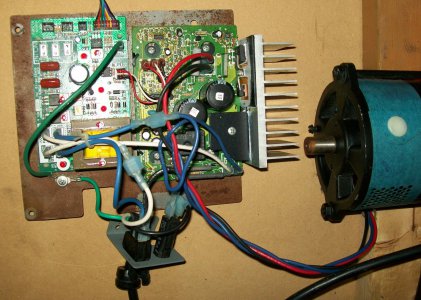
Motor-002.jpg
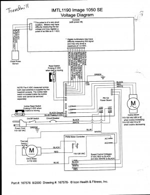
Motor-003.jpg

Motor-002.jpg Motor-003.jpg
 
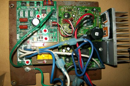
the power board on the left side in the first picture is useless to you for DC drive.
it's for the incline motor, which, by the drawing is an AC motor.
you can remove it from the equation.

just unplug the blue and white from the board on the right, remove the jumper wires to the board on the right.
put the blue and white from the incoming power plug onto the right hand board blue and white terminals respectively.
you will now have 115 VAC~ power to the board.

the board will now need speed control provided by the potentiometer you're going to add.
the small gauge red, black, red wires that were jumping across the 2 boards is the speed control wiring that will be connected to the potentiometer.
5vdc will be control voltage that you will have to supply now that there is no controller RED+.
varying the voltage 0-5vdc with a potentiometer between WHITE+ and BLACK- varies the boards output.
i'm not sure the right ohm rating for your application, but a 500 ohm should work for experimentation.
you may be able to get away with a lower value in real life running.

[you may wish to check the little yellow transformers output, it just might be the 5v you need(it may read 7.5v without a load but you'll need to use a bridge rectifier to get DC signal and you'll have a small voltage drop.)] otherwise you could step higher voltages from the transformer down to acceptable levels with inexpensive voltage regulating semiconductors, or opt for a simple solution like a plug in cell phone wall charger, their voltage is 5vdc and could be easily utilized as the power source.
good luck
mike:))
 
Last edited:
Thank you Mike.
Not sure that all makes sense to me yet, maybe when I'm out to the shop it will start to click.
Wes
 
we can take it real slow, no worries.
you can print out my response and take it out to the shop with you.
it might make it a little easier
 
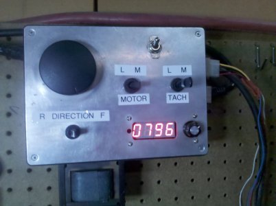
I have done the same thing on my 12 X 36 and am very happy with the results. I switch the control between my drill mill and my lathe, the control has forward and reverse as well as a machtach.

I'll stay out of the conection discussion as Mike knows what he is doing and to many cooks in the kitchen cause confusion.


IMG_20141018_175415.jpg

Art B

IMG_20141018_175415.jpg
 
I have done the same thing on my 12 X 36 and am very happy with the results. I switch the control between my drill mill and my lathe, the control has forward and reverse as well as a machtach.

I'll stay out of the conection discussion as Mike knows what he is doing and to many cooks in the kitchen cause confusion.

Art B


Thanks Art,
feel free to help out if you have other things to add .
i don't have all the answers to everything, that is for sure!
thank you for your kind words.
mike:))
 
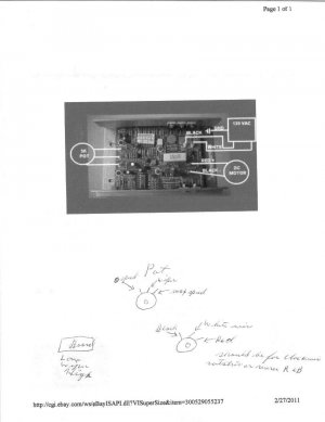
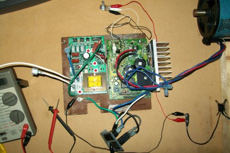
A quick update on my DC motor project. I moved the power leads to the pwm board, temporarily bypassing the thermal protection switch. I unplugged the small red/black/white jumper wires between the boards. In their place I used jumper wires to a 5k linear pot. (My brain told me to buy a 5k instead of 500 ohm as suggested. why does it do that to me? ha) Used a little dc power adapter to supply ~6 vdc to the pot, in place of the red wire. The pic below shows the latest setup.
The results were that the motor would be still. Turning the pot, I'd hear a click & the motor would spin up to a fast speed. There was little resolution on the pot adjustment, so yes must get a lower value resistance.. Then will try again.
Am I placing the pot & power lead correctly?

Motor-Rewire01.jpg

Motor-Rewire01.jpg
 
Back
Top