- Joined
- Feb 8, 2014
- Messages
- 11,144
This is a re-post. The original seems to have gotten lost somewhere, but this question seems to come up often enough that it's worth putting up again.
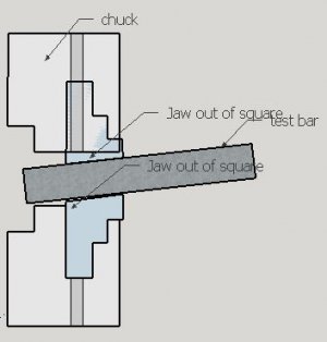
Normally you don't concern your self too much with the accuracy of an independent 4-jaw chuck, but when the centerline of the jaws point somewhere other than the centerline of the lathe it is a bit difficult to overlook.
I purchased this 12-inch chuck off of Craigslist a couple of years ago for $50, and it mostly lives in the tool cabinet. It looked brand new, and I don't think it had ever been on a lathe, it was drilled for use on a rotary table. I have used it for a couple of non-critical jobs, holding some odd shaped parts, but I normally just use my 3-jaw.
The other day a customer brought in a pinion shaft for a Ford 9 inch rear end, and wanted to use a non-stock bearing on it, some kind of a performance mod. OK, yeah, I can fit the new bearing to the shaft. There is no margin for error on this one so out comes the 4-jaw. So I chuck up the shaft, dial it in with a tenth reading indicator, have it right on 0. Life is good.... NOT. I move the carriage down the shaft to indicate another area and the indicator goes off scale. HUH? I'm pretty sure those two surfaces were factory ground in the same setup so they should in the same plane. The shaft is lined up in the chuck jaws but it's pointing to somewhere other than the tail stock center. I handed the shaft back to the customer and told him I can't do the job today.
This chuck is another fine example of work from The Peoples High Precision Chuck Factory #3. When I bought the chuck it came without a back plate so I ordered one from Enco. Apparently it was also made in the above factory. When I got the back plate it seemed to mount OK on the spindle and I fitted it to the chuck. I was in a hurry and didn’t do a lot of check out as I should have, but I didn’t need to use the chuck right then and had another project to do.
How to fix a chuck.
First I remove the jaws and checked the face runout, a couple of thou out at the outer diameter, OK, no problem.
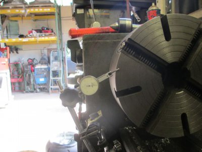
So just to establish a datum point I took a light cut on the face.
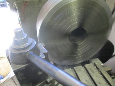
And a light cut on the back outer flange, just to get 2 parallel surfaces.
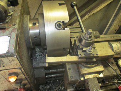
Showing how I ground the tool for clearance.
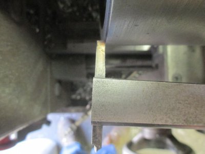
Then I removed the back plate and over to the mill for some measuring.
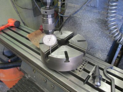
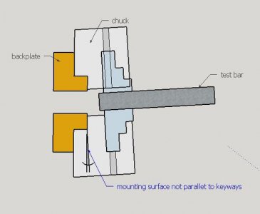
These are the values I got without the 0.010 shim under the left side. I thought about supporting the chuck on the keys and milling the mounting flange, but decided against it. I decided that the best way to square everything up is to put the chuck on a shaft in the lathe and square up the mounting surface to the jaws. .
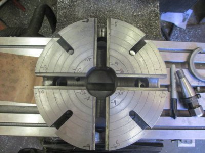
Next I check the jaw keyways for squareness to the jaw face, not very good but I’m not going to grind them right now. There is enough straight material to do the machining on the back.
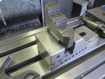
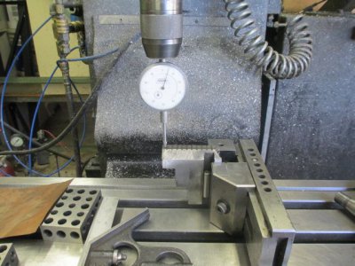
The jaws have always been much too tight in the slots, so I need to fix this first. This is how far the jaws would push in by hand before they got too tight. The t-slots are cut tapered in the chuck body, and I don’t have a t-slot cutter that will get in there to clean them up. So I decided to use an alternate method, not the best, but it will work fine.
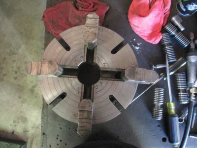
Over to the disk sander and hand fit each jaw to a slot. Just a little bit at a time, work slow and careful. Don’t want them loose. Now the fit is good.
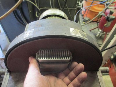
OK, mount the chuck up in the lathe on a piece of 1 inch TG&P (Turned, Ground & Polished) SS shaft that I had kicking around. I chose this because it would fit in the 5C collet chuck (that was also built in the above factory, see the link for more info on that one) http://www.hobby-machinist.com/show...-D1-4-Cam-Lock?p=211256&viewfull=1#post211256
Yes, that t-slot in face is angled off about 10 degrees or so, another example of fine quality control.
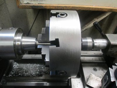
Once I get it zeroed in the z-axis it’s time to check just how far out the mounting surface is…. 0.005 TIR. This pretty much matches the readings I got on the mill.
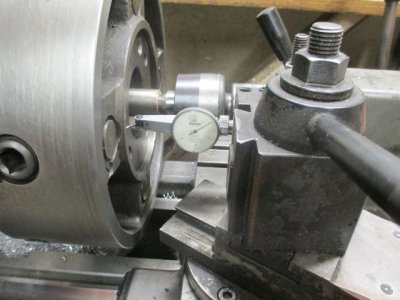
Because of the clearances in my setup, the only way I could reach the face was with a boring tool. I ground a little extra side clearance angle on the tool so it would not hit the edge flange. I can’t take any off of that because it already fits the back plate, and it is concentric with the chuck body. The goal here is just to square up the flat the mounting surfaces to the jaws. After facing I went in and made a small under cut in the corner so that there would be no interference with the back plate edge.
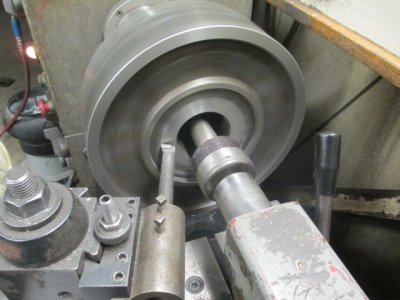
After facing both the internal mounting surface and the flange, and fitting the depth to the back plate depth, I installed the back plate and took some indicator readings, on the spindle mounting surface. It turns out that the back plate was subject to the same ridged quality control standards as the chuck. Not only was it ‘’lumpy’’, about 0.003 TIR at three high spots, it was also cupped, by about 0.004. A very light facing cut on it fixed that problem, and for some reason did not seem change to fit on the spindle taper. It seems to fit fine, the taper and the flange fit as they should. This tells me that the fit was not correct from the factory, and what I did corrected the problem that I didn’t know it had. Normally you would have to bore the taper after facing the mounting face to get a proper fit up.
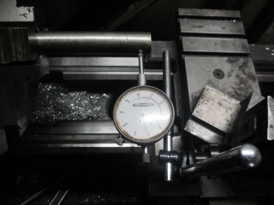
After mounting the chuck and dialing in the shaft right at the chuck jaws, I moved the indicator out to about the 4-inch point and checked there, the difference was about 0.0002. I can live with that.
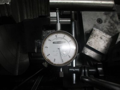
The next step will be to grind the jaw faces to square them up the to key slots. I’ll do this on the surface grinder if I ever get it set up. That will be a thread for another day,
Normally you don't concern your self too much with the accuracy of an independent 4-jaw chuck, but when the centerline of the jaws point somewhere other than the centerline of the lathe it is a bit difficult to overlook.
I purchased this 12-inch chuck off of Craigslist a couple of years ago for $50, and it mostly lives in the tool cabinet. It looked brand new, and I don't think it had ever been on a lathe, it was drilled for use on a rotary table. I have used it for a couple of non-critical jobs, holding some odd shaped parts, but I normally just use my 3-jaw.
The other day a customer brought in a pinion shaft for a Ford 9 inch rear end, and wanted to use a non-stock bearing on it, some kind of a performance mod. OK, yeah, I can fit the new bearing to the shaft. There is no margin for error on this one so out comes the 4-jaw. So I chuck up the shaft, dial it in with a tenth reading indicator, have it right on 0. Life is good.... NOT. I move the carriage down the shaft to indicate another area and the indicator goes off scale. HUH? I'm pretty sure those two surfaces were factory ground in the same setup so they should in the same plane. The shaft is lined up in the chuck jaws but it's pointing to somewhere other than the tail stock center. I handed the shaft back to the customer and told him I can't do the job today.
This chuck is another fine example of work from The Peoples High Precision Chuck Factory #3. When I bought the chuck it came without a back plate so I ordered one from Enco. Apparently it was also made in the above factory. When I got the back plate it seemed to mount OK on the spindle and I fitted it to the chuck. I was in a hurry and didn’t do a lot of check out as I should have, but I didn’t need to use the chuck right then and had another project to do.
How to fix a chuck.
First I remove the jaws and checked the face runout, a couple of thou out at the outer diameter, OK, no problem.

So just to establish a datum point I took a light cut on the face.

And a light cut on the back outer flange, just to get 2 parallel surfaces.

Showing how I ground the tool for clearance.

Then I removed the back plate and over to the mill for some measuring.

These are the values I got without the 0.010 shim under the left side. I thought about supporting the chuck on the keys and milling the mounting flange, but decided against it. I decided that the best way to square everything up is to put the chuck on a shaft in the lathe and square up the mounting surface to the jaws. .

Next I check the jaw keyways for squareness to the jaw face, not very good but I’m not going to grind them right now. There is enough straight material to do the machining on the back.


The jaws have always been much too tight in the slots, so I need to fix this first. This is how far the jaws would push in by hand before they got too tight. The t-slots are cut tapered in the chuck body, and I don’t have a t-slot cutter that will get in there to clean them up. So I decided to use an alternate method, not the best, but it will work fine.

Over to the disk sander and hand fit each jaw to a slot. Just a little bit at a time, work slow and careful. Don’t want them loose. Now the fit is good.

OK, mount the chuck up in the lathe on a piece of 1 inch TG&P (Turned, Ground & Polished) SS shaft that I had kicking around. I chose this because it would fit in the 5C collet chuck (that was also built in the above factory, see the link for more info on that one) http://www.hobby-machinist.com/show...-D1-4-Cam-Lock?p=211256&viewfull=1#post211256
Yes, that t-slot in face is angled off about 10 degrees or so, another example of fine quality control.

Once I get it zeroed in the z-axis it’s time to check just how far out the mounting surface is…. 0.005 TIR. This pretty much matches the readings I got on the mill.

Because of the clearances in my setup, the only way I could reach the face was with a boring tool. I ground a little extra side clearance angle on the tool so it would not hit the edge flange. I can’t take any off of that because it already fits the back plate, and it is concentric with the chuck body. The goal here is just to square up the flat the mounting surfaces to the jaws. After facing I went in and made a small under cut in the corner so that there would be no interference with the back plate edge.

After facing both the internal mounting surface and the flange, and fitting the depth to the back plate depth, I installed the back plate and took some indicator readings, on the spindle mounting surface. It turns out that the back plate was subject to the same ridged quality control standards as the chuck. Not only was it ‘’lumpy’’, about 0.003 TIR at three high spots, it was also cupped, by about 0.004. A very light facing cut on it fixed that problem, and for some reason did not seem change to fit on the spindle taper. It seems to fit fine, the taper and the flange fit as they should. This tells me that the fit was not correct from the factory, and what I did corrected the problem that I didn’t know it had. Normally you would have to bore the taper after facing the mounting face to get a proper fit up.
After mounting the chuck and dialing in the shaft right at the chuck jaws, I moved the indicator out to about the 4-inch point and checked there, the difference was about 0.0002. I can live with that.


The next step will be to grind the jaw faces to square them up the to key slots. I’ll do this on the surface grinder if I ever get it set up. That will be a thread for another day,


