Another VFD question, sorry :(

dado5

Registered
Registered
Joined
Dec 10, 2012
Messages
31
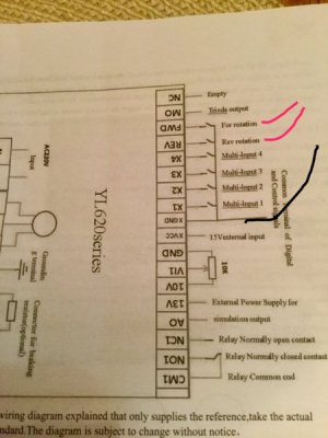
I just acquired an excello mill and am trying to wire it up. I have a Chinese vfd 2.2kw. I have it wired and it works fine controlling the mill from the vfd itself. I am now trying to wire the drum switch to start/stop and fwd/reverse. here is a pic of the diagram for the vfd
IMG_0098.JPG
I found two circuits on the drum switch with one common between them. I hooked the common up to ground (black wire) and the other 2 red wires to fwd, and rev on the vfd. When I switch the drum switch it tries to start and just bumps the mill motor ahead a little at a time. Now I am realizing that I may have only hooked up the controls for fwd/rev and not start/stop but I cant find them on the vfd circuit. I did program it to receive the command source from external control, I just am not sure I am actually hooked up to it right. Any ideas?
 
I wonder do you need to use one of those multi-inputs for start/stop? Maybe somebody will chime in on this...Mike? Jim? Ken?
Mark
 
There is no start/stop switch in 2 wire VFD control. There is only forward and reverse with a sustained contact, stop is when no contact is made. Also 3 phase drum switches have connecting wires that reverse a set of motor poles. There is 3 wire VFD control which uses momentary start stop with a sustained on switch for reverse, but some VFDs do not support this mode. It would also require reprogramming the VFD inputs. Also be sure that the VFD parameters are correctly programed for the motor specs, as well as the other parameters. I have some parameter files for HY VFDs, but everythone seems to be different, so I would need to look at the one for your specific VFD to provide any specific advice. Sorry, but I usually recommend going with something like a Teco L510 or and Automation Direct GS2/GS3 as a started VFD.

I would get rid of the drum switch since the contacts are usually burnt. Get your self a 3 way rotary switch, ON-OFF-ON. The x GND or common goes to the input of both switch terminals (contact block or 2 pole switch), the FWD is connected in the forward position the REV is connected in the reverse position. The motor is directly connected to the VFD. Take a picture of your VFD terminals, the HY manual may be confusing, normally the inputs are connected to the DCM terminal but seems like it might be different in yours.

3 Way switch GCX1320-22
https://www.automationdirect.com/ad...a-_Non-Illuminated/Non-Illuminated/GCX1320-22

Legend Plate E22NS50
https://www.automationdirect.com/ad..._Pushbutton_Accessories/Legend_Plates/E22NS50

In the switch above, you would only use the two normally open (green) contact blocks. IN the center position, neither is engaged. You can also purchase a 2 pole 3 way rotary switch on eBay or elsewhere, but you need to be aware of which contacts are closed in each position.
 
Thanks for the info, i figured it out. I had the wires for the switching running alongside the motor wires back to the vfd. I must have been getting interference, i separated them and now it works perfect
 
Cool! I was just going to ask if you had the control and power wires bundled together-I think the cheaper VFDs are more sensitive to that;
they skimp out on the bypass capacitors and RF chokes necessary to prevent interference
Mark
 
Just another, and probably unnecessary caution: :cautious:

Reputable manufacturers warn against putting any switching on the output of the VFD. The coils in the motor store energy. Should the switch be activated when the motor is turning or when there is still a potential on the windings, the reconnection to the VFD can generate significant voltages - in the thousands of volts, and completely fry your output stages. :faint:
 
Just to clarify, I don't have the switching on the output of the vvd. The vfd is directly connected to the motor. I am using the control circuitry in the vfd for the switching. I would rather have a better drive but this one "came" to me almost free so I thought i would try to use it. So far its working fine.
 
Good that you found the issue and it is working for you. It also a good reminder not to run the communications/input cables close to the motor cable and that the use of shielded cabling with proper grounding of the shield is important to minimize the noise contamination. I usually try to keep a 4-6" distance between the motor and the communications cable, and often double shielded control cable for longer runs all grounded at the VFD. Even with this, I have run into noise contamination issues with ancillary electronics. In some cases I will also put an input noise filter in the power in line to the VFD. I still have some concerns as to the reliability of the drum switch for passing low level signaling, you may want to carefully sand the contact points to clean them up or consider a new rotary switch at some point as noted. I usually prefer to use 3 wire control for simple installs for safety reasons, but you are replicating the design of the original controls which has been used for decades.

On the VFDs, we use what we have/afford and if it works then that is good. It is just that I have run into numerous issues with the generic HY type VFDs, and they are the only ones that I have seen failures. Some are missing the braking circuitry even though they have the terminals for an external resistor, and often have limited programming features (like 3 wire control). Now that there are reasonably priced alternative VFDs like the Teco L510 in the 1-3 hp range, if one has the option then I recommend something like that as a starting point. In the single phase 5-10 hp the HY are cheap, but according to others that install/repair VFDs, the internals are not rated as such and of questionable quality/design. The few that I have installed, the input/motor terminals were too small for the current capacity.
 
Back
Top