- Joined
- Feb 5, 2015
- Messages
- 662
(This was previously posted some time ago and has been edited for a more general audience. The story began as an evaluation, morphed into what might be a history and finally into future expectations. Other than what has been directly observed or measured, this post can be regarded as speculative (or as machine tool reading entertainment).
Additionally, in the spirit of a home machinist forum, a lot of the information contained here may seem superfluous to older machinists but may be new to the younger hobbyist. This type of machine tool is gradually disappearing, replaced by CNC machining centers. The economics are indisputable but it is nevertheless sad to see the passing of the oldest form of rotary milling machine. It's doubtful that anyone interested in machining at this time will ever have the opportunity to run one of these tools, or even see one.
My monologue is disjointed, I apologize - this was written over a four week period, a paragraph or two each night as I learned about the machine from disassembly, studying old blueprints and from operation. I hope nobody minds if I play around a with the titles of this tale … so here we go …)
Chapter One - UNFULFILLED UNNATURAL DESIRES
I've wanted a horizontal mill for a long time. In some areas of our country these machines are readily available but here in northern California (except near the San Francisco bay area or near Sacramento) forget it ! The population density of my county of residence is less than the equivalent population density of New Zealand and the main industry is logging. (There is some commercial fishing and four or five reservations have casino businesses for tourists that pass through our area.) Looking through the local buy/sell press, woodworking equipment is almost the only machinery listed although there is a LOT of that. Occasionally I spot an ad including the word "mill" but it always describes a truck-towable timber mill. Oh yeah, I looked for a buzz-box welder for almost a year with no luck.
I have a small vertical mill that has been useful for dealing with most of the chores encountered in my former consulting engineering business. Vertical mills are very versatile but small ones are also very "rubbery". Rough-machining ferrous castings, forgings, weldments - or just HRS workpieces - in a small vertical mill can often be an unpleasant experience. The machine might shake and shudder, occasionally exhibiting resonances that vibrate the entire shop floor. (I used to think that the solution was bolting the machine to the concrete shop floor until the last large earthquake left a north-south crack across that floor. I don't want any north-south cracks in my machinery castings.) The use of roughing cutters has been a big improvement but few would question the fact that a small horizontal mill removes material faster than a vertical mill that might weigh twice as much.
It is often said that the right machine will come to those who are patient. After forty-plus years of waiting, I should be about due, right? I see nice-looking photographs of horizontal mills on eBay for good prices but they are located very far away. The condition of these machines is doubtful and only one thing is certain: it's going to be expensive to transport one of them from point "A" to where I live so that I can try it out … not to mention the cost of returning it if I don't like the condition (the probability of which is probably 80% … which might also be the possibility of the seller accepting a return).
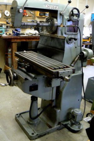
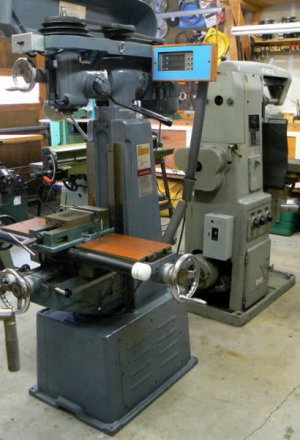
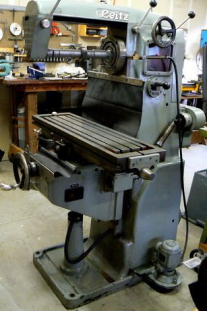
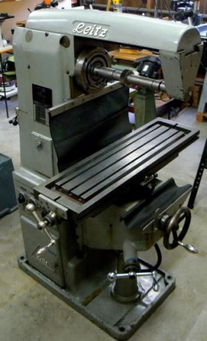
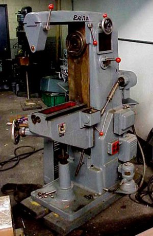
A few weeks ago, I saw a local ad for a horizontal mill, the only ad for ANY kind of metalworking mill that I've seen in my ten years of residence. After a couple of electronic exchanges, I met the owner and inspected the mill without negotiation, following some internet research. (I'm retired and a thrifty person so this is unusual behavior for me. The asking price seemed in line with similar machines on eBay but the condition of the machine was outstanding.) Here is a photo of the horizontal mill behind my small vertical machine on the day that I moved it into my shop.
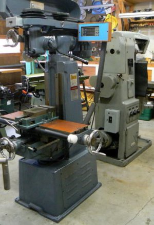
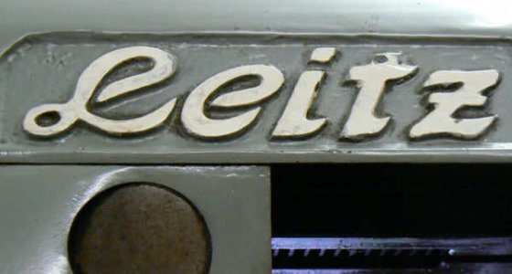
This German-made machine is a Leitz model BMO2/U (10 inch x 36 inch table) universal horizontal mill, serial number 149A (the "U" in the model number indicates a universal table and the "A" in the serial number might denote inclusion of the vertical head). The vertical head is interesting because of a feature seen on a few other horizontal mills. The head attaches to the column (and drive train) with the usual bolted flange but the head is also secured to the over-arm. This is a very rigid configuration compared to a vertical mill of similar size and weight. The vertical head can be rotated about the "Y" and "Z" axes (simultaneously) but naturally cannot "nod" about the "X" axis due to the over-arm connection.
What exactly is a "universal mill" ? This unique machine, so I've read, resulted from the productive "Brown and Sharpe" partnership of the late 19th century. The table, normally the "X" axis, can be rotated around the "Z" axis (+/- 50 degrees - extreme angles may not be achievable with the saddle cranked against the column). A 4th axis (dividing head or rotary table) is always associated with the "universal mill". The rotating device is secured to the table, with the input shaft coupled to the table feed gearing mechanism or independently geared. The rotating device is generally removed when not required - no need for the table to carry the extra weight.
These characteristics are required for many complex milling operations (e.g. helical gears, bevel gears, cylindrical cams, thread milling, rotary and cylindrical valves, fluting of drills and milling cutters and so forth). 3-D geometrical possibilities are surpassed only by 4 and 5 axis machining centers. If one appreciates plane and solid geometry, a universal milling machine is a treasure and a joy to operate - BUT expect to spend time with calculator, gage blocks, DTI and sine bar when making a setup.
This sounds like a serious disadvantage but the upside for old-timers is that the operation of the machine is identical to other manual machinery learned prior to the CNC revolution. For some, the additional set-up complexity and advance planning feels more comfortable than dealing with "G-codes" and other programming skills, not to mention the fact that CNC machinery with the capacity of this horizontal mill is EXPENSIVE !
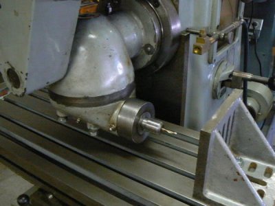
The Leitz vertical head, like many provided with horizontal mills, has no quill. It's not useful for some boring chores that Bridgeport-style vertical machines perform. However, with the support of the over-arm, the head is capable of excellent vertical and angular milling and light horizontal boring performance in a small package. (The qualities of the horizontal spindle are considerably better in most respects.) The following photo shows the head aligned horizontally with the table axis, a six inch angle plate is positioned on the table as a scale reference. (Notice how close to the table the cutting tool can be positioned - much closer than a Bridgeport-style head when rotated to this angle.)
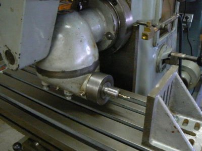
Many boring jobs can be performed with the head in this position (the "X" axis substitutes as a quill - the table is very easy to move and this is the power-feed axis), as well as conventional pocket milling and face milling. The same operations could easily be performed by the horizontal spindle but this configuration is convenient because the cutter is visible from the normal operating position. I feel more comfortable when the cutter is visible and the chips can be easily cleared.
An interesting operation possible with this small machine is thread-milling large diameters (with big thread profiles), normally performed with a multi-ton lathe (or CNC machining center). An example might be short, multiple-start, interrupted buttress threads like those found on breech locking mechanisms of artillery pieces (and also in injection molding machinery). Large diameter internal threading can also be performed using a boring bar in the vertical head configured with spindle aligned along the "X" axis, perhaps with the boring bar supported in a floating or "sliding" rest. Coarse multi-start pitches can be milled in the horizontal spindle while finer pitch milling would be appropriate for the vertical attachment.
When the machine was produced in 1953 there were numerous possibilities for spindle taper configuration and the designers of the vertical head selected one that made sense to them. The taper is 2MT with a 1/2-13 drawbar - unusual because this is the normal drawbar thread size for 3MT collets. (There may be some dispute about the drawbar thread - I've read that some European machinery used a thread of 1/2-12 pitch. That's not the case with this machine since a 1/2-13 tap fully threads into one of the MT collets provided with the head.) I've modified the drawbar to a more standard 3/8-16UNC to suit 2MT collets and readily-available tooling.
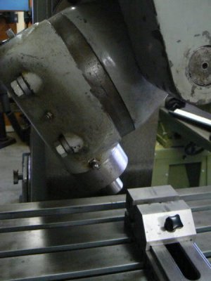
In the following photo, the vertical head is positioned about thirty degrees off the vertical axis. A three inch toolmakers vise is posed on the table to provide a scale reference.
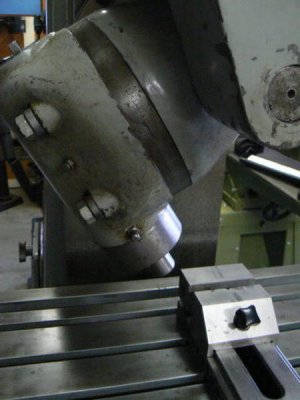
Many interesting possibilities are suggested when combining the vertical head angular capabilities with the universal table, especially for die sinking and pattern making. These capabilities are not within the scope or the interest of the typical HSM, only tool and die makers could take full advantage of them. I am not even close to being a toolmaker but it is satisfying to consider the potential of this machine.
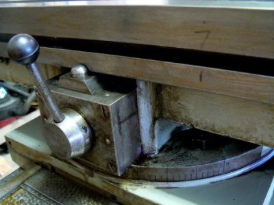
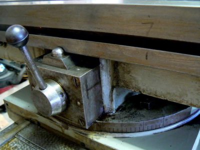
In the following photograph, the table feed engagement lever is shown and the feed disengagement dog. The protractor indicating the table angle is visible in the lower portion of the photo.
This mill has a cast, dovetailed over-arm rather than the more typical American/British style for small horizontals consisting of a single (or pair of) large diameter keyed shaft(s) extending from the top of the mill column. Round over-arms may be more economical to produce but in the case of the single rod configuration might require some "tickling" for precise arbor alignment, if that is critical. (Dual round over-arms and dovetailed configurations normally do not require angular adjustment at the end support.)
The Leitz over-arm can be cranked in/out, like the ram of a vertical turret mill. Three locking clamps, two on the column and one on the end support, secure the over-arm to the machine housing and the arbor. (The shape of many over-arms is semi-parabolic, as a matter of interest. The reason for this shape is that it exhibits equal strength at any load point along the length. This is not true of beams with uniform cross-section.) The over-arm can be used to support any arbitrary (shorter) length arbor just like a lathe tailstock. The three clamps and the over-arm crank are visible in the following photo. At the base of the column casting, the coolant pump can be seen.
The over-arm crank is especially useful when installing and removing the vertical head, which is compact but heavy. Here's how it works for me: after placing the vertical head on the mill table supported by protective wood scraps, the table can be raised until the support lug of the head is roughly aligned with the end support bore. The end support is slid along the over-arm (while adjusting the height with the "Z" axis crank) until the bore is engaged with the vertical head mounting lug.
The end support is then locked into position on the over-arm. Now all that is required is to crank the over-arm inboard until the end support is seated over the mounting lug of the vertical head. Once the head is supported by the end support, the over-arm crank can easily move the over-arm + head until the vertical head is aligned with the horizontal spindle drive and mounting studs. It's a purpose that the designers doubtless intended since the chance of bunging up dimensions is great when mating heavy objects to precisely machined features.
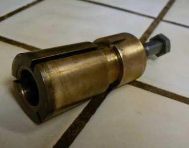
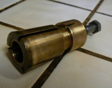
The outboard support can be locked at any position along the over-arm to best support the tooling in use at the time. Heavy-duty cuts are best made with short arbors to maximize support. The outboard support bearing is bronze and configured like a short R8 collet. After the arbor journal is slipped into the bearing, the bearing is withdrawn into the tapered socket of the outboard support with a short "drawbar" screw and the outboard support is clamped to the over-arm. The running clearance of the bearing can be easily adjusted for the spindle speed and degree of accuracy required. (Using modern machinery with tapered roller bearing spindles, this is no longer the "learned" procedure it once was. The procedure is simple, however: adjust the end support bearing, lubricate, then rest a hand on the bearing support occasionally to test running temperature, adjusting and oiling as required.)
The only incidence of misuse that I've noted in this machine is the face of the outboard support bearing. It is visibly evident that no thrust washer was installed between the bearing and the arbor and the arbor has worn an impression on the bearing. I've made a thrust washer, of course, since the photograph was snapped. (By the way, bronze bearings are normal in most small horizontal mills, they are appropriate for fairly low speeds and high pressure levels.)
The bronze end support bearing must be removed when using the over-arm to support the vertical head. The first time that I installed the vertical head, I took the opportunity to carefully measure and record dimensions of the bearing for inclusion in the documentation file for the machine. In the event a new bearing should be required, every operation can be performed in one lathe setup except for the bearing bore. The bearing needs to be installed in the end support then bored in place to maintain factory alignment. Like an R8 collet, a pin in the end support mates with a slot in the bearing. (This isn't for "anti-rotational" purposes but so that exact alignment with the spindle is assured when the bearing has been removed and consequently reinstalled.)
Chapter Two - THE FLASHBACK
This horizontal mill was formerly owned by the state university down the road and used in a fuel cell development laboratory. Thirty or forty pages of original paperwork, including blueprints originally shipped with the mill (I hadn't seen a "blueprint" in thirty years and some of these are in German), were part of the purchase package. Among the paperwork was the purchase order (signed by the laboratory's "principal investigator") and a sales receipt from 1992 indicating that the mill was purchased (used) for $3,486 U.S. + $125 shipping, from the San Francisco area to our university in northern California. The documentation provided with the machine is best described as "internal" documentation - it's not what one would expect to be provided to a buyer.
Most of the operational documents are hand-made drawings and tables, rendered and hand-lettered in pencil. CAD documentation was unknown in 1953 but even so there were many different means of producing quality documentation: long-carriage typewriters specifically designed for drafting applications, "Leroy" mechanical inking sets with various fonts and text sizes, many types of lettering templates and so forth. Not to mention the various processes developed by the advertising industry such as photo-lithography, "rub on" transfer lettering, cut/paste artwork, air-brush re-touching and so forth.
Coincidentally, the manufacturer of the mill (Leitz) made many products to support drafting and illustration technologies, I owned quite a few of them. My point is that the operating documentation is very primitive in appearance (and not all that accurate, as will be discussed presently). Since most of the precision drafting and lettering tools of that period were made in Germany it's curious that they weren't used in the creation of the document package that accompanied the mill. Some drawings are "freehand" sketches - no drafting instruments were used to produce them, not even a straight-edge.
It is extremely unlikely that this package would have been provided to a "customer". As an example of the rough documentation, while examining the speed/feed charts I noticed several errors resulting from lettering transpositions - not uncommon in casual documentation that didn't undergo a rigorous checking process. Further, in some of the drawings of the drive train, some important details were omitted: a belt drive in one drawing and a compound gear in another. (Because of light sensitivity, after photographing the originals, I've stored them for the next lucky owner of the Leitz.)
I read an opinion from an internet site suggesting that Leitz didn't make this model for external sale - that the machines were built only in sufficient quantities to support their camera-making operations in Germany. This might explain why I'm unable to find mention of this mill model on the internet, as I'll mention later. (If anyone can provide sources of information regarding these machines, I'd be grateful.)
The prospect of learning about a quality piece of machinery that was apparently not produced for export (maybe not even for sale) is intriguing. Perhaps the machine wasn't sold outside of the company because the market wouldn't bear production costs plus reasonable profit ? There were many highly competitive European manufacturers of similar machines.
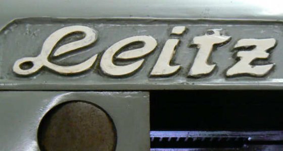
There is an alternative "history", too. I've read speculations that Leitz didn't make some of the machinery used on their camera-making line. There are suggestions that these machines were produced by another manufacturer (who wasn't mentioned) and the two or three external parts with the "Leitz" logo cast into the pattern don't necessarily provide bona fide origins for the machinery. Knowing little of the company, the machine, the competing manufacturers or much else, anything that I write other than direct observation is personal speculation, LOL.
The past 175 years produced a heritage of machine tools - mostly in the U.S. and Europe - that changed the world. In recent years, we have become exposed to phrases like "supporting the brand", "brand recognition", "brand loyalty" and other "brand" inclusive phrases - applicable even to political parties, apparently. The facts are that manufacturing brands mean little, the world's low-cost manufacturing base is now China and most former producers of quality machinery simply paste a label on imported products, collect the profits and don't think about the skilled workers that lost their jobs.
This is a preface to the next segment of this discussion. I asked the man from whom I purchased this machine (who operated the mill for the university and eventually bought it from the university) for comments he might think useful to my understanding and interest in the Leitz. I didn't suggest speculative theories but interestingly he e-mailed the following message:
"I can relate a story told by the engineer who obtained that mill for the lab where I worked. He was told that the mill was made for Leitz in their own shops, for their own use in the U.S. It is hard to imagine the effort that went into that machine if that story is true... I mean, all the patterns and one-off machining, these days of "let the other guy do it" are so removed from the time when boys were brought through a system of apprenticeship and became highly skilled and dedicated craftsmen, able to make machine tools and their own measuring and layout tools themselves....it really breaks my heart to think what we have lost, maybe forever.
I frequently think about this, looking at the machines that I own, thinking about the machine shops that have gone bust around here and the factories that have disappeared across the country ... you could name the companies that have disappeared, pushed into the scrap heap by accountants and lawyers. It really brings tears to my eyes to think that at one time you could buy a steam locomotive almost entirely made here in Eureka (I figure the pressure gauges were made elsewhere, but who knows, all those guys are dead!).
Back to the subject of the Leitz, maybe the folder I gave you has a date somewhere, I never read most of the stuff in the folder, and if you have, you may know more than I do. There was a CNC technician for "Performance Machine Tools" in Fremont, who I think was maybe one of those guys who always had to seem as if he knew everything, but he said he had heard of the Leitz mill, like maybe there was more than one of them, but maybe he was full of crap....hard to tell!"
Resuming the story from my own viewpoint, someone at the university apparently desired this machine for a specific purpose. Paperwork included with my purchase was collected in a manila file folder, on the cover of which a hand-written list of names and telephone/FAX numbers is prefaced by: "try to find a contact for machines made for camera work", which is interestingly suggestive.
Most of the names on the list seem to be German and two of the five are individuals employed by different divisions of Leitz (in the U.S.) at the time. I have no idea what this machine made for the university but "someone" apparently desired a machine that was capable of some "grunt" as well as some precision since several used Bridgeport vertical mills in fine condition could have been obtained for that amount of money at that time in "Silicon Valley" - the location of the purchase.
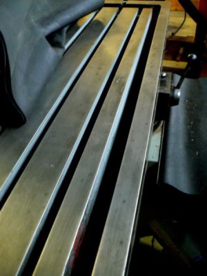
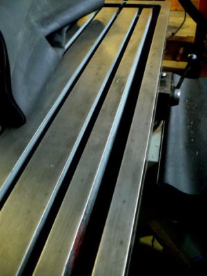
This mill has been very gently used - leadscrews are exceptionally tight and the table is free of marks except for some stains. The paint on this fifty-seven year old machine looks pretty good compared to my ten-year old vertical mill with a single owner. It can be observed from some of the photos of the Leitz that an operator took the time to make nice way protectors (from natural rubber, too). I don't know which of the owners added these but apparently he valued the mill. (I've removed them for a few of the photos, by the way.) Here's a photo of the table - no dings or scratches but a few stains:
Before buying the mill, I noted that the slides felt "tight" but wasn't able to measure the play until the machine finally came home. Indicating the "Y" slide, I measured the play across the full travel range to be less than .007 inches. The "Z" axis indicated backlash of .004 inches max over the full travel and the "X" axis indicated a backlash of .006 inches over the full range. (Needless to say, after making these measurements, I considered the age of the machine then repeated the measurements !)
When my new (Taiwan) vertical mill was delivered ten years ago, I measured and recorded the backlash on all axes (after snugging the adjusters) and found about .005 - .007 play. The backlash deteriorated to about .008 - .011 after approximately ten hours of usage and re-adjustment. The backlash is now about .013 after some estimated 400 total hours of operation. Tightening the knee gib lock causes considerable deflection at the vise location (measured from the quill with a .0001 DTI) while the Leitz doesn't deflect measurably when the "Z" gib is locked or unlocked. (The machine has dual gib locks, one on either side of the knee so that lateral play is effectively equalized/cancelled when both are snugged.) I haven't encountered an operation that required the use of the gib locks but clearly they are there for a reason which I'm sure to discover in time.
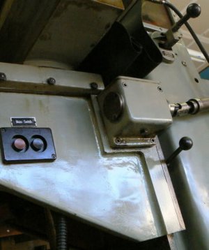
Here's a photo, snapped from underneath the table. One of the two knee locks is visible as is the master switch, the spindle transmission gear selector and one of the universal joints from the table feed transmission. It's also possible to see the rotating table interface.
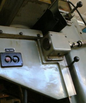
The "Z" axis dial is graduated in .0005 inch increments while the "X" and "Y" axes are graduated in .002 increments - all dial movements agreed perfectly with the travel indicator used to make the measurements. The "X" and "Y" axes move on gibbed dovetail ways while the "Z" axis is an enclosed "box" configuration. This is a European practice that is sensible because "Z" ways partially support the husky knee, the table and the tooling in addition to substantial cutting loads and therefore should be more rugged with better wear characteristics than the dovetailed axes. This seems to be a successful strategy based on the fact that the "Z" axis measurement exhibited considerably less play than the other two axes despite supporting much heavier loads. (The "box" configuration is visible in the photo.)
Backing up for a moment, it's not my intention to find fault with the workmanship of the Taiwanese mill, although it is clearly not in the same league as the old German machine. I would simply note that the "Enco" labeled machine is an example of a design that has been developed only to the extent necessary to perform to a certain standard. Specifically, there's no real advantage in making the column and base of a vertical mill as massive as that of a horizontal mill. The flexible nature of the vertical design is such that extra column mass would not significantly add to rigidity but would add substantial material/labor cost and weight.
Chapter Three - A RELATIONSHIP WITH TWO WOMEN IN THE SAME HOME
I've been spending so much time learning about the Leitz - my wife has started to call it "your elderly German girl-friend.
My two milling machines are almost exactly the same height and take up the same amount of floor space (within an inch or two). But it can be seen from the initial photograph that the Leitz has a generous cross-sectional column, compared to the Taiwanese vertical mill (not to mention some four hundred pounds of additional mass). One night I made an estimate of the sectional modulus (a measure of "stiffness") of both machines based on column measurements and found the Leitz - on paper - to be four times more rigid which "feels" about right to me.
This is further supported by the amount of metal that I've removed with the Leitz so far, LOL, compared to similar operations performed on the "Enco" branded machine.
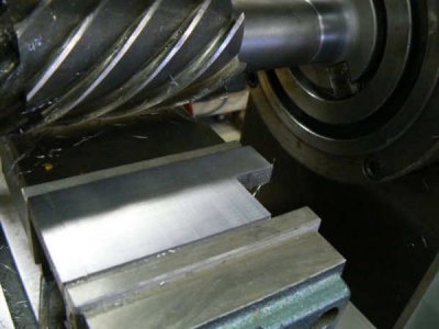
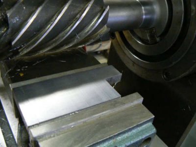
It is very difficult to make some comparisons between the two types of machinery, some operations are a natural for one machine while other operations are completely inappropriate. Here's an obvious horizontal operation: slab milling:
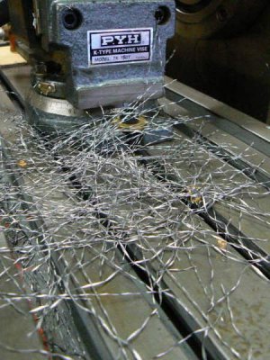
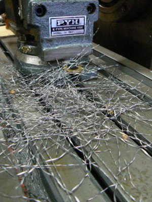
Some of the chips produced by the previous operation (LOL - this was a FINISHING pass). Many years ago when I worked at Westinghouse Marine Division, I used to watch the operators of large horizontal mills using a pitchfork to transfer the chips from their machine into a wheelbarrow !
In the above case, the workpiece was 4 x 2 x 1/2 inches of hot-rolled steel. The DOC was 1/8 inch and one cubic inch of material was removed in a single pass in 45 seconds leaving a surface finish of 32 microinches, mainly due to the very high helix angle and the number of teeth on the cutter.
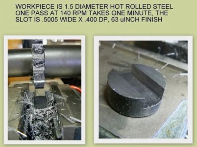
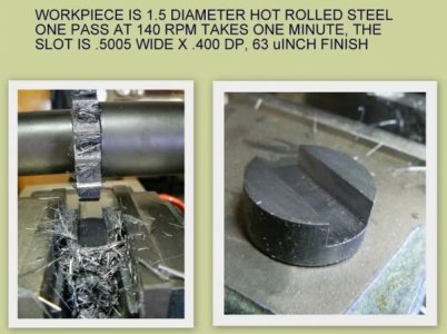
Another obvious example is slotting. I performed a timed example, the arbitrary example was a machine clutch dog, where the depth of the slot was not critical but the width was desired to be within +.003/-.000 inches. The surface finish was arbitrarily specified at 63 microinches (not necessary for performance requirements but consistent with tolerance and measurement uncertainty). Using a slotting cutter, the Leitz produced the slot in one pass and the resulting width was measured at .5005 - surface finish easily met 63 microinches.
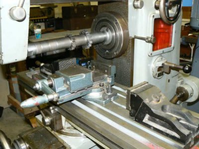
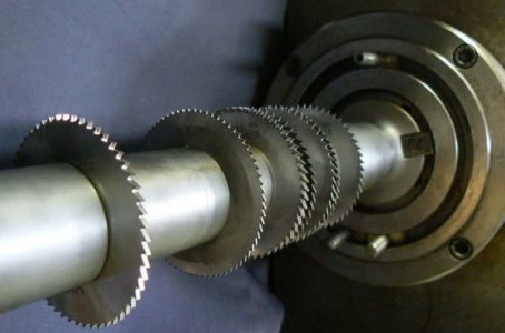
Several slotting cutters mounted on an arbor:
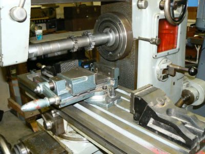
The same operation on the small vertical mill required four passes with a new 3/8 cutter, two to rough to depth and two to finish both sides and depth. The cutting time was about the same as above (one minute) but the machine had to be adjusted four times and two measurements made during the process. Total time required to produce the slot was about three minutes. The time is noted as a matter of interest only, both milling machines are ideally suited for applications for which the other is NOT equally suited. This experiment indicated, in a way, why the horizontal mill was so prevalent for mass production and the vertical mill dominated model shop usage.
The required slot could be reproduced for hours on the horizontal mill without concern for tolerance or surface finish (until the cutting edge degraded) by an unskilled operator. The same operation performed on a vertical mill introduces operator error at several critical points and requires a level of skill beyond that of "crank-turner".
When small CNC machinery became economically feasible then the vertical machine could perform the same operation in LESS time (higher spindle speeds) using the same "crank-turner" as the horizontal machine previously required. Tooling costs were a fraction of those required by the horizontal machine - end mills are "throw-aways" while slotting cutters are definitely NOT !
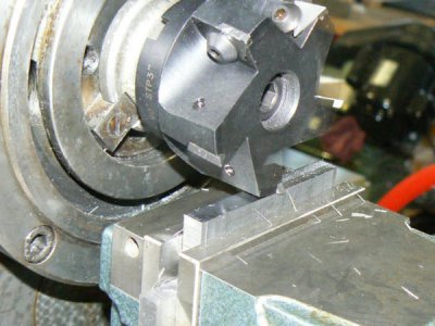
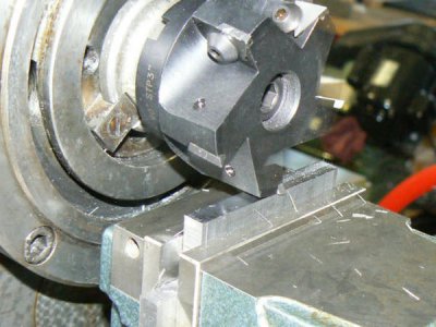
The following depiction is a 2-1/2 inch shell mill with carbide inserts in a NMBT-40 holder. The machine was making a finish cut on 1/2 HRS without coolant, when I snapped the flash photo. The strobe flash did a good job of freezing cutter rotation and shows the fine finish that can be available from this type of tooling in a horizontal mill. (If the job was run in a vertical mill of the same size/weight, this surface finish would be unachievable without spending a lot more time.)
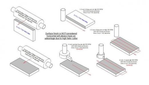
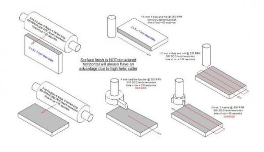
Here's a series of sketches that I was working on as I thought about how certain operations are "natural" for one type of milling machine compared to another type - the little sketches are self-explanatory, I think, in case the lettering on the sketches is difficult to read:
After measuring table travels and backlash, I measured arbor runout with the 1 inch arbor installed. This was a parameter about which I'd been concerned since internet knowledge states that old horizontal mills "always" have bent arbors, right ? The runout measured .750 from the spindle face was .0003 and the runout 13 inches away, at the end support, was less than .0010. The lower surface of the arbor was parallel to the "Y" axis travel and the table surface within .0005 across the full arbor length. (I didn't check "X" axis perpendicularity to the spindle since the "universal" table can be adjusted to any angle within any practical degree of accuracy.)
I am resisting the inclination to "pretty up" this machine. I didn't buy it because it was special - I didn't even realize that it WAS special at the time that I signed the check. It's intended mostly for the hard work that my small vertical mill can't perform effectively. The mill has a great deal of dignity just as it stands and needs little more from me than to turn cranks, switches and feed levers - and keep it lubricated !
It's worth repeating that I've wanted one of these small horizontal mills for a LONG time. This machine will be cared for with respect but I don't have the time, the knowledge and the capability to groom it to "show quality". I love to see posts by those who have restored wonderful old machines to factory pristine condition. In fact, of all the threads that I read THOSE probably occupy 60% of my attention (and everyone else's, LOL).
The machine was qualification tested on 11 August 1953 before delivering to "William Lohn" (whose organization and nationality were not recorded). The final test data and certificate of compliance is included in the package, inspected and signed by Herr "Griim" at the Leitz factory. Guaranteed performance parameters are shown side-by-side with the measured data and indicate a comfortable amount of margin. The metrology seems to have been developed with typical German thoroughness; sometimes several different measurement techniques were used to determine the same specification. Here's the well-worn factory folder that contains the original documentation from 1953.

Included in the paperwork are setup tables for simple indexing, differential indexing and helical milling in addition to other information. The history from 1953 to 1992 left no trail in the records that came with the machine but I suspect that a lot of that time was spent in storage. I'm slightly familiar with the machine tool distributor that sold this used mill to the university in 1992 (I did business with them in earlier years) but they are no longer in business. This is purely speculative but from the limited wear, the unflawed table, the excellent condition of the gears and belts - just the overall appearance - this machine may have been used in the model shop of an electronics company, probably a start-up. In the time period encompassing 1955 - 1980, thousands of small electronics companies sprang up and disappeared in the Santa Clara Valley (Silicon Valley). I was fortunate enough to have participated in several - interesting times providing great experience.
At that time, it was customary that model shops were operated by a toolmaker and it follows that a skilled craftsman would have cared for his equipment. An indication of care - or lack of use - is the fact that the ten plastic knobs, seven levers and four hand-wheels are intact and undamaged with not a single crack in any of the plastic knobs. The hand-wheels and dials are discolored in areas that might be consistent with long-term storage. About 90 degrees of the dials are "varnished" by oil residue, maybe from the normal leakage of table lubricants slowly flowing downward around dials and handles. Perhaps the mill saw a few years of service with limited use and then was stored until the purchase in 1992.
Chapter Four - BACK TO THE PRESENT
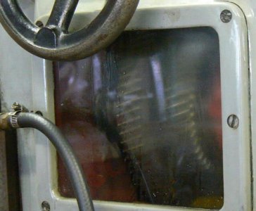
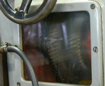
The mill has factory coolant provisions although the flow routing appears to have been configured for a specific operation at the university lab. Combinations of speeds and feeds are as expected in a machine originally designed for toolroom use. There's no need to wonder about oil level in the transmission, a window in the side of the column allows observation of the quiet helical main drive train during operation. One of the blueprints shows all of the bearing locations in the drive and feed trains - there are no single-row bearings in the machine, all are duplex (with the likely exception of main drive motor and coolant pump). The photo below shows the spindle transmission after operating the mill - it's a little hazy because the inside of the window is still covered with oil flung from the gears. (The black hose connects the coolant pump with the spray head near the arbor.)
There is a lubrication chart in the drawing package (convenient when fittings are not placed in obvious, visible positions as is the case with this machine). This used to be one of the most important documents provided with a machine tool - now it seems almost a rarity. I can't complain much about this since one-shot oilers have become common in many milling machines. It's so much easier to make a single squeeze of the pump every morning and afternoon rather than tickling twenty little ball-spring fittings with a tiny oil can.
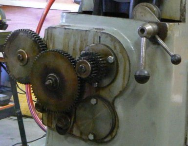
Here's a photo of the feed transmission with the cover removed, taken the day I moved the machine into my shop.
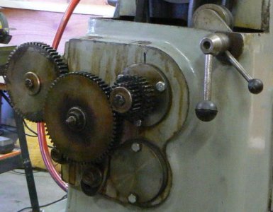
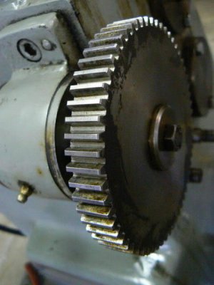
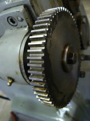
After removing the change gears for cleaning, I took the following photo of the primary feed gear. Note that there are virtually no signs of wear on the gear.
According to the included drawing of the Leitz vertical milling head (Model BMC 100) the lower bearings in the vertical spindle appear to be ball thrust bearings rather than angular-contact or tapered-roller bearings. This seems odd but I'm not familiar with the design conventions of European machine tools although I know that they are at least as robust and accurate as those produced in this country. On the same drawing are detailed instructions providing a step-by-step adjustment procedure for minimizing spindle play.
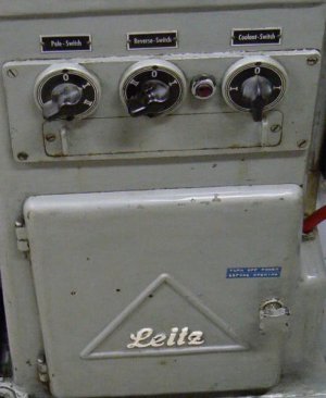
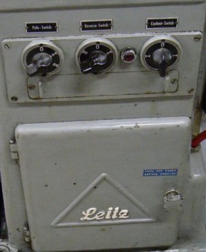
The primary drive is a conventional four-step pulley, belt-driven from a 2 horsepower three-phase motor mounted in the base of the machine, to a countershaft. The countershaft splits the drive between spindle and feed transmissions. A high-low gearshift on the column allows 3.175:1 spindle speed change without affecting the table feed rate and the three-phase drive motor is dual speed with 2:1 ratio, which does affect the table feed. According to the documentation provided with the machine, there are fifteen close-ratio speeds from 62 to 910 RPM and the sixteenth is a large step from 910 to 1820 RPM, probably intended for the vertical head. The following photo portrays the motor speed control, forward/reverse switch, pilot light and the coolant pump switch. The cast door under the panel provides access to the main drive motor for changing belt position on the drive pulleys and the coolant tank.
None of the old "chicken head" style "Bakelite" switch knobs are chipped or cracked.
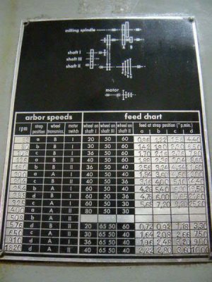
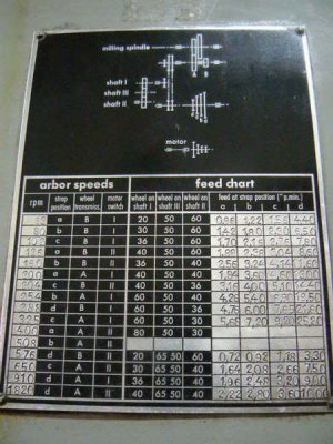
The speed range is appropriate for HSS cutters as large as 7 inches diameter for ferrous work. Using carbide insert tooling, larger diameter cutters can make short work of roughing and finishing nasty materials, provided that the operator can work out a secure clamping scheme. Below is a photo of the speed/feed chart mounted on the left side of the column. Feed data use the European convention of the comma (rather than a decimal point) to indicate fractional parts.
On this nameplate and throughout the documentation, there is a translation error, the word "strap" is used instead of "belt" (as in "drive belt"). The nameplate may (or may not) have been silk-screened - speed and feed values were entered with a typewriter. This wasn't a highly unusual practice for equipment with various options; silk-screened parameters were readily removed with an "electric eraser", a common drafting implement of the time (which Leitz also manufactured).
Note also the fact that the feed values were unintentionally omitted for the spindle RPM of 400 (the feeds should have been approximately double those listed for 200 RPM) and that NO gear selections OR feeds are specified for the spindle speed of 508 RPM. These are further hints that this may not have been a production machine, more on this later.
When I first saw the mill, I hoped that the gear ratio of the vertical head would be about 1.5:1 which would provide speeds ranging from 100 to 3,000 RPM, similar to most "modern" vertical mills. That wasn't the case, the ratio is 1 : 1. Perhaps during the era that the machine was designed, HSS end mills hadn't achieved metallurgical qualities that allowed higher speeds. It won't be a problem for me since high speed milling is an assignment better suited to my small vertical mill - the horizontal was purchased for different work (e.g. heavier milling and larger diameter boring).
Thinking aloud, a future project might entail making an adjustable cradle for a die grinder if the die grinder bearings could be replaced with precision parts. Held between over-arm and main spindle, this might make an acceptable high-speed spindle for small carbide end mills since the machine itself is tight and robust enough to support the use of solid carbide tooling. I have tried small, solid-carbide end mills in a router motor secured to the quill of a vertical mill with no success - router motors are entirely too flexible.
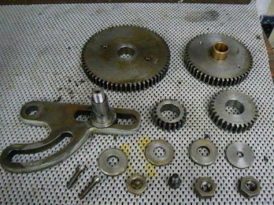
Longitudinal table feeds are seen to be adjustable from fractions of an inch per minute to 25 inches per minute and can be disengaged with table stops. The feed transmission is engaged when the primary motor is operating, regardless of whether the table feed is enabled (unless the banjo gear is disengaged). This may have been intended because the designers envisioned driving a rotary mechanism while the table remains stationary. Here is a photo of the banjo and some of the change gears, note the carefully machined spiral oil groove on the idler bushing. That is consistent with all of the bushings in the machine that I have disassembled and examined. The difference from the few "chisel scratches" that are called oil grooves on many imported machines should be apparent.
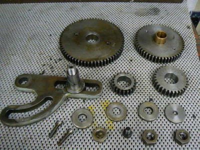
The machine has imperial dials and leadscrews rather than metric - an unlikely option given the heritage of the company and their product lines but implies the intended use of the mill in the U.S. perhaps in one of the several Leitz subsidiaries that existed then and now. There are fifteen different feed combinations listed on the nameplate and, like the speeds, they are close-ratio. It's difficult to imagine a situation where this machine couldn't be optimized for a particular task within its working envelope. (Note that all of the various nameplates, including the speed/feed chart, are in English.)
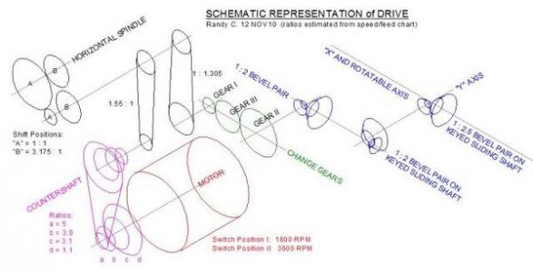
Noting the sketchiness of the original documentation, I made an effort to understand the drive and feed trains so that I could determine how best to set up the machine for various chores. The feed requires the use of change gears, as in a lathe, to make use of the "universal" qualities of the mill. The feed (and rotary mechanism when installed) must be synchronized to the spindle - unlike the typical power feed drives on vertical mills which are unsynchronized - unless the purpose is simply to move the table without having to crank the handles, LOL. During the process of determining the drive and feed train configurations, I found a number of errors.
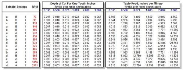
I don't personally find the travel rate (inches per minute) as useful as I do chip load (or table movement per spindle revolution). That information can be obtained by dividing the RPM by IPM and then dividing the result by the number of cutter teeth. But I'd just as soon have a table in the shop that shows BOTH the travel rate and the chip load. A few minutes work with a spread sheet can provide both that information as well as ANY combination of change gears on the banjo.
A further problem when using European machinery in the U.S. is the difference in power line frequencies. European standard requires 50 Hz operation while the U.S. uses a 60 Hz standard. If the line voltages are the same then a European machine, like the Lietz will run faster by the ratio of 60 : 50. If the voltages are not identical, the speed will also vary. At any rate, I wanted to correct for the errors that will necessarily be reflected on the machine's nameplate and internal documentation.
Most importantly, after I traced the feed train through the machine I noted (as mentioned elsewhere) that the spindle gearshift did not affect the feed rate however the nameplate and the internal documentation do not reflect that fact. Both indicate a feed rate change of 2: 1 when the selector is shifted which is not the case. Other errors and omissions have been noted previously. I'm speculating that the original German documentation was incorrectly translated here in the U.S. or that a detailed drive drawing was not provided so that the feeds could be calculated properly. The sketchily prepared blueprints were replicated, mostly, by the person who added the typed figures to the nameplate. Oddly, the two transcription errors that I found on the blueprint didn't occur on the nameplate.
Obviously, I did not want to disassemble the machine to count gear teeth and measure pulleys so some of this information is inferred from the included documentation, estimates, axis travel measurements, leadscrew pitch and the like. In other words, some of the internal ratios are estimates but I'm confident enough about the overall ratios to be able to select the proper change gears for a specific task with confidence. Here is a CAD sketch of the drive train as I now understand it (a printout of which will be added to the original documentation); the change gear train is indicated by gears I, II and III in the sketch:
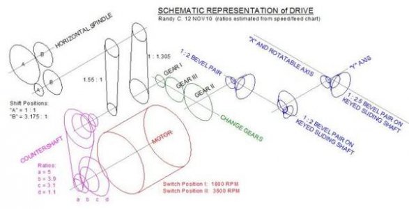
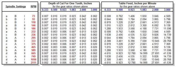
For convenience, I have simplified the feed gearing scheme to six combinations that, in conjunction with drive belt changes, produce feed rates from 0.5 to 41 IPM in steps of about 1.3 : 1. The highest feed rates would not be useful for most metalworking applications but are suitable for gang-sawing aluminum and hardwoods. The maximum spindle speed of about 2100 RPM is a good one for working hardwoods. Here is a copy of the spread sheet that I generated with the six gearing combinations, including the change in line frequency and the inclusion/correction of errors in the data provided with the machine:
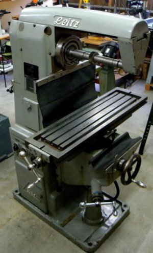
For the HSM (ignoring other interesting features) the desirability of this machine is size: an estimated 1600 pounds (stripped) in an envelope just slightly greater than my small 8 x 30 vertical mill weighing in at 1200 pounds. Before picking up the mill, I spent an evening working with my CAD shop layout until I was sure that this mill would be a comfortable fit in my small shop. No problem - the Leitz doesn't hog space and push the Taiwanese machine off to the side, LOL, despite its seniority and higher-precision heritage.
Moving the machine was straightforward enough, despite the fact that I was working solo. Careful planning, considering each move and every possibility, is necessary when moving heavy machinery without assistance. I spent about three hours the night before the move trying to anticipate each tool, timber, clamp, come-along, wedge, strap, hydraulic jack, pipe roller and so forth - each time I remembered an item, I placed it in the back of the borrowed truck. (I would have liked to photo-document the process for the benefit of those who haven't done this type of chore before but it just wasn't practical.)
Here's another photo of the mill from a different angle before the coolant drain hoses were connected.
As a new owner, I'm subject to the auto-mechanism requiring defense of my purchase (although this was NOT an impulse buy, having waited forty years for a horizontal mill). It probably seems that I'm overly praising this machine so it is time to address some of the drawbacks.
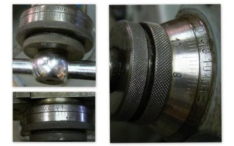
Although the machine has imperial dials, there is an anomaly: the "Y" axis is .160 inches/revolution rather than .200/revolution or .100/revolution as are the "X" and "Z" controls. That's strange and baffling - would it not have been just as simple to install 5 or 10 pitch lead screws in this axis (rhetorical question) ? I can't see any overwhelming disadvantage to this yet but I would definitely not like the arrangement on a vertical mill where the "Y" axis is used as frequently as the "X" axis. Here are photos of the dials.
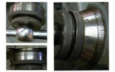
The leadscrews were not the ones that the original designers intended for this machine, so someone (probably here in the U.S.) made "sort-of" imperial dials. The work was apparently performed by scribing/hand-stamping and doesn't come close to the standards of German workmanship that would be expected of this machine, in my opinion.
If this mill was the only one in my shop, I would find the maximum speed of the vertical head (2100 RPM) marginal for nonferrous materials. The rigidity and precision of this machine practically begs for solid carbide end mills, but the spindle speeds can't take advantage of modern tool technology, at least for the vertical head. The 2MT collet capability of the vertical head also limits the size of end mill shanks.
The stout vertical head, given the spindle speeds available, CAN make efficient use of larger end mills and shell mills. Rather than continue to use 2MT collets, I purchased a 2MT/ER-40 collet chuck (because I want to standardize to ER-40 for all of my small machinery, where possible). The drawbar was modified for the collet chuck threads and also to accommodate the standard 3/8-16 thread of most Morse taper collets. Although it would be great to have a higher speed vertical spindle, it's not that important - I don't mind breaking down a setup on the other vertical mill now that I'm retired.
I wanted a horizontal mill for its obvious abilities and the available speed range is fine for the horizontal spindle of this machine. The horizontal taper allows for more serious tooling. The ER-40 collet system that I chose probably won't be used often in the horizontal spindle except for drill chucks, an occasional, rare end mill and - probably most useful - a boring head. (To expand the use of the ER-40 collets, I also acquired an R8 collet chuck for the vertical mill, in the event a gripping diameter requirement arose that an R8 collet couldn't satisfy.)
I've been interested in using this machine for boring since I purchased it, I see good possibilities for small jobs using the horizontal spindle. Recently, I found a press release from the "Criterion" organization, noted for their very fine boring heads. The release emphasized an expansion of their product line that acknowledged the growing use of ER style collet systems. Here is a paragraph from the release that attracted my attention:
"The ER32 and ER40 sizes are available with a 0.000050-inch on-diameter micro adjusting dial. The largest bore diameter the CBER system can produce is 1.7 inch; the smallest is 0.035 inch, although compatible boring tools for diameters below this size are available from other suppliers, Mr. Wahlstrom reports."
I'm not sure that I can ever justify purchasing one of these fine boring tools now that my "business" has reverted to "hobby" by Internal Revenue Service definitions, LOL. But I have seen straight-shank boring head arbors (imported) for $15 and I plan to order one soon. I can switch off my regular three inch head from the R8 arbor to the straight shank and then try it out with a NMBT/ER-40 collet chuck in the Lietz horizontal spindle.
I suppose that the single greatest disadvantage of this purchase is that if a critical part breaks on this machine there are no replacements. To my knowledge there are few machines like this; I found ONE after extensive internet searching. Leitz is active in heavy woodworking machinery (here in logging/mill country but especially in Europe). The parent company, which includes six multi-national divisions, still advertises metalworking machinery but I could not identify any conventional milling machines in their product line. They do make high-end metalworking machinery (like precision gear hobbers) and more esoteric machinery for working quartz and optical glass blanks but that sort of equipment is out of my budget and my needs, LOL.
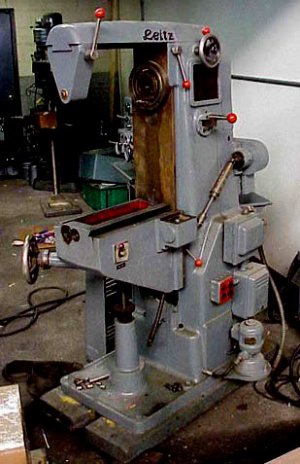
This is a photo of the "other" Leitz universal horizontal mill that I found on the "Practical Machinist" forum, it was posted some years ago. The table has been removed from this machine and the short post made no explanation for this. Variations compared to my mill include the paint color of the corporate logo, configuration of the main power switch, location of electrical junction boxes and the color of the molded plastic control ends on the various rods and levers. Doubtless the switch and the junction boxes differ between the European model and the one configured for the U.S. I cannot detect - at least from this single photograph - any functional differences.
The Leitz company, established in 1876, has a fine reputation as a quality manufacturer of microscopes, cameras, movie projectors, high-precision optics, specialized tooling including precision coordinate measurement equipment, optical comparators and surveying equipment. Older members may recall that the company also made drafting instruments and slide rules (I may still own a stainless-steel compass stamped with the logo). They competed with companies like "Dietzgen", "Brunton", "Keuffel and Esser" and similar respected German and European manufacturers of precision equipment.
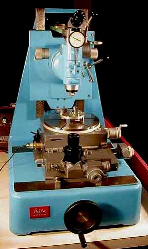
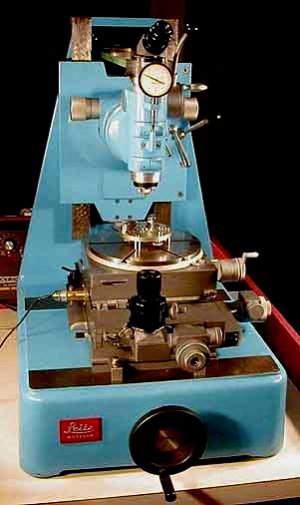
I've read that Leitz jig-borers were considered superior to Swiss "Hauser" machines (made in larger quantities and presumably more available). I have no idea as to the accuracy of that opinion and can no longer recall its source (chances are it was also "Practical Machinist" because I spent a lot of time on that forum in the past decade). However, the one or two Hauser jig borers I've seen were very fine machines and I'll leave quality resolution to the tool and die makers. Here is a photo of a small Leitz boring machine used for the manufacture of wrist-watch parts (during the time when wristwatches were completely mechanical):
Chapter Five - CLEAR AND PRESENT SATISFACTION
I would have been satisfied with a Burke, a Millrite, an Atlas, Sheldon, Clausing, Hardinge, Vernon, Tom Senior, Benchmaster or ANY of the excellent small American or British machines of the 1920-1960 era. I didn't imagine finding a machine in the condition of this one (especially with a "universal" table AND a vertical head) and it's doubtful that I will use 40% of the capability of this mill. There is no functional feature of this machine that doesn't work today to the exact specification for which it was designed (and to which it was tested on 11 August 1953).
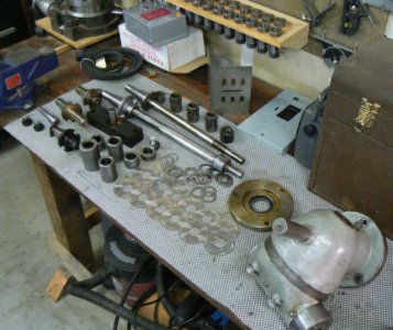
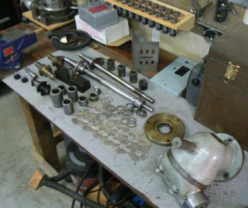
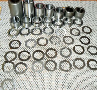
Two full-length arbors, 7/8 (left hand) and 1 inch (right hand), were included with the machine as well as a one inch diameter stub arbor (also used to drive the vertical head), a one inch shell mill holder, a small end mill holder, a dozen slotting cutters and an large assortment of ground arbor spacers for both arbor diameters (including many 1 inch adjustment spacers in increments of .002 to .020 thickness as well as the normal larger spacers - very nice). The horizontal spindle is a NMBT-40 taper, also nice.
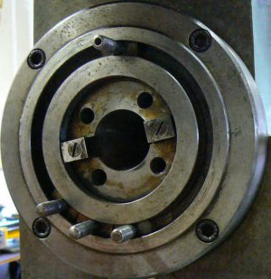
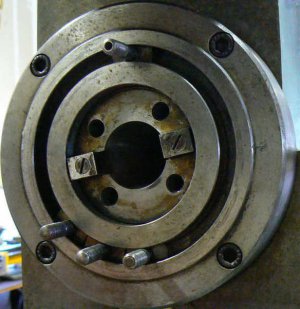
There is a spare set of belts - one for the motor drive and one for the countershaft. Here's a photo of some of the tooling and also one of the horizontal spindle taper (the studs for attaching the vertical head are still dangling from the mounting flange). A lot of the tooling isn't shown and there are two or three large pieces whose purposes I have yet to determine. I suspect that they are for mounting the dividing head and gearing to the table feed.
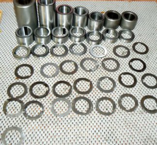
Although a number of 1 inch arbor spacers were provided with the mill (down to .002 inches) I happened to find a very nice set of ground spacers of various increments (3.000 inches down to .010 inch) at a good price. I was cruising the site looking for something else and these caught my eye:
Tooling for horizontal mills is considerably more expensive than for verticals, as one would expect given that the cutters contain some twenty to forty times more material and the many extra cutting surfaces that require grinding. I have no problem justifying the extra cost because these machines remove metal so effectively - especially facing, slotting, sawing and 2-D contouring. "Buy it now" pricing on eBay seems to reflect import tool pricing and it's doubtful that any bargains can be obtained from purchasing single cutters.
Reading the experiences of those who often buy from eBay suggests that bargains are more likely obtained from "lot" purchases. Lot purchases can be a grab bag, of course, unless one is prepared to sharpen cutters. But if one has the time and the willingness to experiment, this might be productive even without a T/C grinder. I have an appalling vision of someone tossing sharp-edged cutters into a box at an auction then later cynically wrapping them individually to ship to an eager buyer, LOL, although I hope that I'm wrong.
A typical situation envisioned for a hard-working horizontal machine: stacked face, side and slotting cutters - ganged to produce an entire finish-dimensioned profile with multiple features. That won't be a common situation in my tiny shop (with a few possible exceptions). My requirements can be satisfied with six or eight slotting cutters, two slab mills and a couple of shell insert heads (maybe a dovetail cutter). A few tools used in the vertical mill could also be used in the horizontal using the ER-40 system, small slotting cutters for example.
I mentioned a few exceptions and these apply mostly to the use of metalworking tools for woodworking, as described in this link:
http://hobby-machinist.com/index.php?PHPSESSID=89a2fc888f1089a7a36c08c348bcc9f1&topic=407.0
My father-in-law (retired lumber mill saw-filer, millwright and skilled furniture maker) has accumulated a number of molding and shaper heads over his very active ninety years. I can visualize producing short lengths of fancy molding using shop-made HSS tooling at 2100 RPM in the Leitz using three or four molding/shaper heads on a single arbor. Even at some of the maximum table feed rates, a smooth finish should be obtainable in most hardwoods, grain orientation permitting. This is just one of the reasons I've desired one of these machines for many years - to support my woodworking efforts in addition to metalworking.
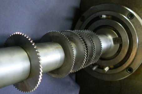
A very useful function is breaking down stock. Sawing is usually the most efficient and the least wasteful means for the HSM. A small horizontal mill can saw precisely - with no further finishing operations normally required - two inch thick material and greater. Multiple saw blades can be ganged on an arbor to break down stock into multiple different-sized parts in a single pass like the following setup for slicing 1/4 aluminum plate using the internal coolant pump system.
An application appropriate to some of the development work that I have done is making custom heat exchangers to support high power solid-state electronic designs. Convection cooled heat sinks are readily obtainable but forced air cooling scenarios nearly always require more sophisticated design procedures and specifically-machined parts, rather than catalog items.
Another potential project for a woodworker who owns a universal horizontal mill might be making a jointer cutting head that accepts insert tooling. I like spiral jointer heads but they are costly and not justifiable to a thrifty hobbyist like me. Given a source of inexpensive inserts appropriate for shaping hardwoods, a spiral jointer head (schedule 160 pipe and a little welding for example) could be a simple chore given the helical capabilities of a universal mill. And then no more worries about running over hidden nails in reclaimed hardwood.
Using a high-speed spindle (e.g. a converted die grinder as mentioned above), I can envision using the geared rotary table to perform scrolling and decorative fluting tasks on hardwood and nonferrous materials. The effect on brass or aluminum candlesticks, for example, would be very attractive I imagine.
I spent the greater part of two months divesting numerous bulky items to open up floor space in my little shop. It seems that I was destined to find this Leitz just a few weeks after completing that task. I may never discover the history of this machine during the years for which I have no documentation - unless by some one-in-a-million chance a reader might know something about these mills. Nevertheless, it's been fun reading through the old prints and trying to determine what the machine was used for in the past. As for the future, there's little doubt that the little machine will perform capably any task to which I can apply it.
Oh yes, purchase price ? $1000

Additionally, in the spirit of a home machinist forum, a lot of the information contained here may seem superfluous to older machinists but may be new to the younger hobbyist. This type of machine tool is gradually disappearing, replaced by CNC machining centers. The economics are indisputable but it is nevertheless sad to see the passing of the oldest form of rotary milling machine. It's doubtful that anyone interested in machining at this time will ever have the opportunity to run one of these tools, or even see one.
My monologue is disjointed, I apologize - this was written over a four week period, a paragraph or two each night as I learned about the machine from disassembly, studying old blueprints and from operation. I hope nobody minds if I play around a with the titles of this tale … so here we go …)
Chapter One - UNFULFILLED UNNATURAL DESIRES
I've wanted a horizontal mill for a long time. In some areas of our country these machines are readily available but here in northern California (except near the San Francisco bay area or near Sacramento) forget it ! The population density of my county of residence is less than the equivalent population density of New Zealand and the main industry is logging. (There is some commercial fishing and four or five reservations have casino businesses for tourists that pass through our area.) Looking through the local buy/sell press, woodworking equipment is almost the only machinery listed although there is a LOT of that. Occasionally I spot an ad including the word "mill" but it always describes a truck-towable timber mill. Oh yeah, I looked for a buzz-box welder for almost a year with no luck.
I have a small vertical mill that has been useful for dealing with most of the chores encountered in my former consulting engineering business. Vertical mills are very versatile but small ones are also very "rubbery". Rough-machining ferrous castings, forgings, weldments - or just HRS workpieces - in a small vertical mill can often be an unpleasant experience. The machine might shake and shudder, occasionally exhibiting resonances that vibrate the entire shop floor. (I used to think that the solution was bolting the machine to the concrete shop floor until the last large earthquake left a north-south crack across that floor. I don't want any north-south cracks in my machinery castings.) The use of roughing cutters has been a big improvement but few would question the fact that a small horizontal mill removes material faster than a vertical mill that might weigh twice as much.
It is often said that the right machine will come to those who are patient. After forty-plus years of waiting, I should be about due, right? I see nice-looking photographs of horizontal mills on eBay for good prices but they are located very far away. The condition of these machines is doubtful and only one thing is certain: it's going to be expensive to transport one of them from point "A" to where I live so that I can try it out … not to mention the cost of returning it if I don't like the condition (the probability of which is probably 80% … which might also be the possibility of the seller accepting a return).
A few weeks ago, I saw a local ad for a horizontal mill, the only ad for ANY kind of metalworking mill that I've seen in my ten years of residence. After a couple of electronic exchanges, I met the owner and inspected the mill without negotiation, following some internet research. (I'm retired and a thrifty person so this is unusual behavior for me. The asking price seemed in line with similar machines on eBay but the condition of the machine was outstanding.) Here is a photo of the horizontal mill behind my small vertical machine on the day that I moved it into my shop.

This German-made machine is a Leitz model BMO2/U (10 inch x 36 inch table) universal horizontal mill, serial number 149A (the "U" in the model number indicates a universal table and the "A" in the serial number might denote inclusion of the vertical head). The vertical head is interesting because of a feature seen on a few other horizontal mills. The head attaches to the column (and drive train) with the usual bolted flange but the head is also secured to the over-arm. This is a very rigid configuration compared to a vertical mill of similar size and weight. The vertical head can be rotated about the "Y" and "Z" axes (simultaneously) but naturally cannot "nod" about the "X" axis due to the over-arm connection.
What exactly is a "universal mill" ? This unique machine, so I've read, resulted from the productive "Brown and Sharpe" partnership of the late 19th century. The table, normally the "X" axis, can be rotated around the "Z" axis (+/- 50 degrees - extreme angles may not be achievable with the saddle cranked against the column). A 4th axis (dividing head or rotary table) is always associated with the "universal mill". The rotating device is secured to the table, with the input shaft coupled to the table feed gearing mechanism or independently geared. The rotating device is generally removed when not required - no need for the table to carry the extra weight.
These characteristics are required for many complex milling operations (e.g. helical gears, bevel gears, cylindrical cams, thread milling, rotary and cylindrical valves, fluting of drills and milling cutters and so forth). 3-D geometrical possibilities are surpassed only by 4 and 5 axis machining centers. If one appreciates plane and solid geometry, a universal milling machine is a treasure and a joy to operate - BUT expect to spend time with calculator, gage blocks, DTI and sine bar when making a setup.
This sounds like a serious disadvantage but the upside for old-timers is that the operation of the machine is identical to other manual machinery learned prior to the CNC revolution. For some, the additional set-up complexity and advance planning feels more comfortable than dealing with "G-codes" and other programming skills, not to mention the fact that CNC machinery with the capacity of this horizontal mill is EXPENSIVE !
The Leitz vertical head, like many provided with horizontal mills, has no quill. It's not useful for some boring chores that Bridgeport-style vertical machines perform. However, with the support of the over-arm, the head is capable of excellent vertical and angular milling and light horizontal boring performance in a small package. (The qualities of the horizontal spindle are considerably better in most respects.) The following photo shows the head aligned horizontally with the table axis, a six inch angle plate is positioned on the table as a scale reference. (Notice how close to the table the cutting tool can be positioned - much closer than a Bridgeport-style head when rotated to this angle.)

Many boring jobs can be performed with the head in this position (the "X" axis substitutes as a quill - the table is very easy to move and this is the power-feed axis), as well as conventional pocket milling and face milling. The same operations could easily be performed by the horizontal spindle but this configuration is convenient because the cutter is visible from the normal operating position. I feel more comfortable when the cutter is visible and the chips can be easily cleared.
An interesting operation possible with this small machine is thread-milling large diameters (with big thread profiles), normally performed with a multi-ton lathe (or CNC machining center). An example might be short, multiple-start, interrupted buttress threads like those found on breech locking mechanisms of artillery pieces (and also in injection molding machinery). Large diameter internal threading can also be performed using a boring bar in the vertical head configured with spindle aligned along the "X" axis, perhaps with the boring bar supported in a floating or "sliding" rest. Coarse multi-start pitches can be milled in the horizontal spindle while finer pitch milling would be appropriate for the vertical attachment.
When the machine was produced in 1953 there were numerous possibilities for spindle taper configuration and the designers of the vertical head selected one that made sense to them. The taper is 2MT with a 1/2-13 drawbar - unusual because this is the normal drawbar thread size for 3MT collets. (There may be some dispute about the drawbar thread - I've read that some European machinery used a thread of 1/2-12 pitch. That's not the case with this machine since a 1/2-13 tap fully threads into one of the MT collets provided with the head.) I've modified the drawbar to a more standard 3/8-16UNC to suit 2MT collets and readily-available tooling.
In the following photo, the vertical head is positioned about thirty degrees off the vertical axis. A three inch toolmakers vise is posed on the table to provide a scale reference.

Many interesting possibilities are suggested when combining the vertical head angular capabilities with the universal table, especially for die sinking and pattern making. These capabilities are not within the scope or the interest of the typical HSM, only tool and die makers could take full advantage of them. I am not even close to being a toolmaker but it is satisfying to consider the potential of this machine.
In the following photograph, the table feed engagement lever is shown and the feed disengagement dog. The protractor indicating the table angle is visible in the lower portion of the photo.

This mill has a cast, dovetailed over-arm rather than the more typical American/British style for small horizontals consisting of a single (or pair of) large diameter keyed shaft(s) extending from the top of the mill column. Round over-arms may be more economical to produce but in the case of the single rod configuration might require some "tickling" for precise arbor alignment, if that is critical. (Dual round over-arms and dovetailed configurations normally do not require angular adjustment at the end support.)
The Leitz over-arm can be cranked in/out, like the ram of a vertical turret mill. Three locking clamps, two on the column and one on the end support, secure the over-arm to the machine housing and the arbor. (The shape of many over-arms is semi-parabolic, as a matter of interest. The reason for this shape is that it exhibits equal strength at any load point along the length. This is not true of beams with uniform cross-section.) The over-arm can be used to support any arbitrary (shorter) length arbor just like a lathe tailstock. The three clamps and the over-arm crank are visible in the following photo. At the base of the column casting, the coolant pump can be seen.

The over-arm crank is especially useful when installing and removing the vertical head, which is compact but heavy. Here's how it works for me: after placing the vertical head on the mill table supported by protective wood scraps, the table can be raised until the support lug of the head is roughly aligned with the end support bore. The end support is slid along the over-arm (while adjusting the height with the "Z" axis crank) until the bore is engaged with the vertical head mounting lug.
The end support is then locked into position on the over-arm. Now all that is required is to crank the over-arm inboard until the end support is seated over the mounting lug of the vertical head. Once the head is supported by the end support, the over-arm crank can easily move the over-arm + head until the vertical head is aligned with the horizontal spindle drive and mounting studs. It's a purpose that the designers doubtless intended since the chance of bunging up dimensions is great when mating heavy objects to precisely machined features.
The outboard support can be locked at any position along the over-arm to best support the tooling in use at the time. Heavy-duty cuts are best made with short arbors to maximize support. The outboard support bearing is bronze and configured like a short R8 collet. After the arbor journal is slipped into the bearing, the bearing is withdrawn into the tapered socket of the outboard support with a short "drawbar" screw and the outboard support is clamped to the over-arm. The running clearance of the bearing can be easily adjusted for the spindle speed and degree of accuracy required. (Using modern machinery with tapered roller bearing spindles, this is no longer the "learned" procedure it once was. The procedure is simple, however: adjust the end support bearing, lubricate, then rest a hand on the bearing support occasionally to test running temperature, adjusting and oiling as required.)
The only incidence of misuse that I've noted in this machine is the face of the outboard support bearing. It is visibly evident that no thrust washer was installed between the bearing and the arbor and the arbor has worn an impression on the bearing. I've made a thrust washer, of course, since the photograph was snapped. (By the way, bronze bearings are normal in most small horizontal mills, they are appropriate for fairly low speeds and high pressure levels.)
The bronze end support bearing must be removed when using the over-arm to support the vertical head. The first time that I installed the vertical head, I took the opportunity to carefully measure and record dimensions of the bearing for inclusion in the documentation file for the machine. In the event a new bearing should be required, every operation can be performed in one lathe setup except for the bearing bore. The bearing needs to be installed in the end support then bored in place to maintain factory alignment. Like an R8 collet, a pin in the end support mates with a slot in the bearing. (This isn't for "anti-rotational" purposes but so that exact alignment with the spindle is assured when the bearing has been removed and consequently reinstalled.)

Chapter Two - THE FLASHBACK
This horizontal mill was formerly owned by the state university down the road and used in a fuel cell development laboratory. Thirty or forty pages of original paperwork, including blueprints originally shipped with the mill (I hadn't seen a "blueprint" in thirty years and some of these are in German), were part of the purchase package. Among the paperwork was the purchase order (signed by the laboratory's "principal investigator") and a sales receipt from 1992 indicating that the mill was purchased (used) for $3,486 U.S. + $125 shipping, from the San Francisco area to our university in northern California. The documentation provided with the machine is best described as "internal" documentation - it's not what one would expect to be provided to a buyer.
Most of the operational documents are hand-made drawings and tables, rendered and hand-lettered in pencil. CAD documentation was unknown in 1953 but even so there were many different means of producing quality documentation: long-carriage typewriters specifically designed for drafting applications, "Leroy" mechanical inking sets with various fonts and text sizes, many types of lettering templates and so forth. Not to mention the various processes developed by the advertising industry such as photo-lithography, "rub on" transfer lettering, cut/paste artwork, air-brush re-touching and so forth.
Coincidentally, the manufacturer of the mill (Leitz) made many products to support drafting and illustration technologies, I owned quite a few of them. My point is that the operating documentation is very primitive in appearance (and not all that accurate, as will be discussed presently). Since most of the precision drafting and lettering tools of that period were made in Germany it's curious that they weren't used in the creation of the document package that accompanied the mill. Some drawings are "freehand" sketches - no drafting instruments were used to produce them, not even a straight-edge.
It is extremely unlikely that this package would have been provided to a "customer". As an example of the rough documentation, while examining the speed/feed charts I noticed several errors resulting from lettering transpositions - not uncommon in casual documentation that didn't undergo a rigorous checking process. Further, in some of the drawings of the drive train, some important details were omitted: a belt drive in one drawing and a compound gear in another. (Because of light sensitivity, after photographing the originals, I've stored them for the next lucky owner of the Leitz.)
I read an opinion from an internet site suggesting that Leitz didn't make this model for external sale - that the machines were built only in sufficient quantities to support their camera-making operations in Germany. This might explain why I'm unable to find mention of this mill model on the internet, as I'll mention later. (If anyone can provide sources of information regarding these machines, I'd be grateful.)
The prospect of learning about a quality piece of machinery that was apparently not produced for export (maybe not even for sale) is intriguing. Perhaps the machine wasn't sold outside of the company because the market wouldn't bear production costs plus reasonable profit ? There were many highly competitive European manufacturers of similar machines.
There is an alternative "history", too. I've read speculations that Leitz didn't make some of the machinery used on their camera-making line. There are suggestions that these machines were produced by another manufacturer (who wasn't mentioned) and the two or three external parts with the "Leitz" logo cast into the pattern don't necessarily provide bona fide origins for the machinery. Knowing little of the company, the machine, the competing manufacturers or much else, anything that I write other than direct observation is personal speculation, LOL.

The past 175 years produced a heritage of machine tools - mostly in the U.S. and Europe - that changed the world. In recent years, we have become exposed to phrases like "supporting the brand", "brand recognition", "brand loyalty" and other "brand" inclusive phrases - applicable even to political parties, apparently. The facts are that manufacturing brands mean little, the world's low-cost manufacturing base is now China and most former producers of quality machinery simply paste a label on imported products, collect the profits and don't think about the skilled workers that lost their jobs.
This is a preface to the next segment of this discussion. I asked the man from whom I purchased this machine (who operated the mill for the university and eventually bought it from the university) for comments he might think useful to my understanding and interest in the Leitz. I didn't suggest speculative theories but interestingly he e-mailed the following message:
"I can relate a story told by the engineer who obtained that mill for the lab where I worked. He was told that the mill was made for Leitz in their own shops, for their own use in the U.S. It is hard to imagine the effort that went into that machine if that story is true... I mean, all the patterns and one-off machining, these days of "let the other guy do it" are so removed from the time when boys were brought through a system of apprenticeship and became highly skilled and dedicated craftsmen, able to make machine tools and their own measuring and layout tools themselves....it really breaks my heart to think what we have lost, maybe forever.
I frequently think about this, looking at the machines that I own, thinking about the machine shops that have gone bust around here and the factories that have disappeared across the country ... you could name the companies that have disappeared, pushed into the scrap heap by accountants and lawyers. It really brings tears to my eyes to think that at one time you could buy a steam locomotive almost entirely made here in Eureka (I figure the pressure gauges were made elsewhere, but who knows, all those guys are dead!).
Back to the subject of the Leitz, maybe the folder I gave you has a date somewhere, I never read most of the stuff in the folder, and if you have, you may know more than I do. There was a CNC technician for "Performance Machine Tools" in Fremont, who I think was maybe one of those guys who always had to seem as if he knew everything, but he said he had heard of the Leitz mill, like maybe there was more than one of them, but maybe he was full of crap....hard to tell!"
Resuming the story from my own viewpoint, someone at the university apparently desired this machine for a specific purpose. Paperwork included with my purchase was collected in a manila file folder, on the cover of which a hand-written list of names and telephone/FAX numbers is prefaced by: "try to find a contact for machines made for camera work", which is interestingly suggestive.
Most of the names on the list seem to be German and two of the five are individuals employed by different divisions of Leitz (in the U.S.) at the time. I have no idea what this machine made for the university but "someone" apparently desired a machine that was capable of some "grunt" as well as some precision since several used Bridgeport vertical mills in fine condition could have been obtained for that amount of money at that time in "Silicon Valley" - the location of the purchase.
This mill has been very gently used - leadscrews are exceptionally tight and the table is free of marks except for some stains. The paint on this fifty-seven year old machine looks pretty good compared to my ten-year old vertical mill with a single owner. It can be observed from some of the photos of the Leitz that an operator took the time to make nice way protectors (from natural rubber, too). I don't know which of the owners added these but apparently he valued the mill. (I've removed them for a few of the photos, by the way.) Here's a photo of the table - no dings or scratches but a few stains:

Before buying the mill, I noted that the slides felt "tight" but wasn't able to measure the play until the machine finally came home. Indicating the "Y" slide, I measured the play across the full travel range to be less than .007 inches. The "Z" axis indicated backlash of .004 inches max over the full travel and the "X" axis indicated a backlash of .006 inches over the full range. (Needless to say, after making these measurements, I considered the age of the machine then repeated the measurements !)
When my new (Taiwan) vertical mill was delivered ten years ago, I measured and recorded the backlash on all axes (after snugging the adjusters) and found about .005 - .007 play. The backlash deteriorated to about .008 - .011 after approximately ten hours of usage and re-adjustment. The backlash is now about .013 after some estimated 400 total hours of operation. Tightening the knee gib lock causes considerable deflection at the vise location (measured from the quill with a .0001 DTI) while the Leitz doesn't deflect measurably when the "Z" gib is locked or unlocked. (The machine has dual gib locks, one on either side of the knee so that lateral play is effectively equalized/cancelled when both are snugged.) I haven't encountered an operation that required the use of the gib locks but clearly they are there for a reason which I'm sure to discover in time.
Here's a photo, snapped from underneath the table. One of the two knee locks is visible as is the master switch, the spindle transmission gear selector and one of the universal joints from the table feed transmission. It's also possible to see the rotating table interface.

The "Z" axis dial is graduated in .0005 inch increments while the "X" and "Y" axes are graduated in .002 increments - all dial movements agreed perfectly with the travel indicator used to make the measurements. The "X" and "Y" axes move on gibbed dovetail ways while the "Z" axis is an enclosed "box" configuration. This is a European practice that is sensible because "Z" ways partially support the husky knee, the table and the tooling in addition to substantial cutting loads and therefore should be more rugged with better wear characteristics than the dovetailed axes. This seems to be a successful strategy based on the fact that the "Z" axis measurement exhibited considerably less play than the other two axes despite supporting much heavier loads. (The "box" configuration is visible in the photo.)
Backing up for a moment, it's not my intention to find fault with the workmanship of the Taiwanese mill, although it is clearly not in the same league as the old German machine. I would simply note that the "Enco" labeled machine is an example of a design that has been developed only to the extent necessary to perform to a certain standard. Specifically, there's no real advantage in making the column and base of a vertical mill as massive as that of a horizontal mill. The flexible nature of the vertical design is such that extra column mass would not significantly add to rigidity but would add substantial material/labor cost and weight.
Chapter Three - A RELATIONSHIP WITH TWO WOMEN IN THE SAME HOME
I've been spending so much time learning about the Leitz - my wife has started to call it "your elderly German girl-friend.
My two milling machines are almost exactly the same height and take up the same amount of floor space (within an inch or two). But it can be seen from the initial photograph that the Leitz has a generous cross-sectional column, compared to the Taiwanese vertical mill (not to mention some four hundred pounds of additional mass). One night I made an estimate of the sectional modulus (a measure of "stiffness") of both machines based on column measurements and found the Leitz - on paper - to be four times more rigid which "feels" about right to me.
This is further supported by the amount of metal that I've removed with the Leitz so far, LOL, compared to similar operations performed on the "Enco" branded machine.
It is very difficult to make some comparisons between the two types of machinery, some operations are a natural for one machine while other operations are completely inappropriate. Here's an obvious horizontal operation: slab milling:

Some of the chips produced by the previous operation (LOL - this was a FINISHING pass). Many years ago when I worked at Westinghouse Marine Division, I used to watch the operators of large horizontal mills using a pitchfork to transfer the chips from their machine into a wheelbarrow !

In the above case, the workpiece was 4 x 2 x 1/2 inches of hot-rolled steel. The DOC was 1/8 inch and one cubic inch of material was removed in a single pass in 45 seconds leaving a surface finish of 32 microinches, mainly due to the very high helix angle and the number of teeth on the cutter.
Another obvious example is slotting. I performed a timed example, the arbitrary example was a machine clutch dog, where the depth of the slot was not critical but the width was desired to be within +.003/-.000 inches. The surface finish was arbitrarily specified at 63 microinches (not necessary for performance requirements but consistent with tolerance and measurement uncertainty). Using a slotting cutter, the Leitz produced the slot in one pass and the resulting width was measured at .5005 - surface finish easily met 63 microinches.

Several slotting cutters mounted on an arbor:

The same operation on the small vertical mill required four passes with a new 3/8 cutter, two to rough to depth and two to finish both sides and depth. The cutting time was about the same as above (one minute) but the machine had to be adjusted four times and two measurements made during the process. Total time required to produce the slot was about three minutes. The time is noted as a matter of interest only, both milling machines are ideally suited for applications for which the other is NOT equally suited. This experiment indicated, in a way, why the horizontal mill was so prevalent for mass production and the vertical mill dominated model shop usage.
The required slot could be reproduced for hours on the horizontal mill without concern for tolerance or surface finish (until the cutting edge degraded) by an unskilled operator. The same operation performed on a vertical mill introduces operator error at several critical points and requires a level of skill beyond that of "crank-turner".
When small CNC machinery became economically feasible then the vertical machine could perform the same operation in LESS time (higher spindle speeds) using the same "crank-turner" as the horizontal machine previously required. Tooling costs were a fraction of those required by the horizontal machine - end mills are "throw-aways" while slotting cutters are definitely NOT !
The following depiction is a 2-1/2 inch shell mill with carbide inserts in a NMBT-40 holder. The machine was making a finish cut on 1/2 HRS without coolant, when I snapped the flash photo. The strobe flash did a good job of freezing cutter rotation and shows the fine finish that can be available from this type of tooling in a horizontal mill. (If the job was run in a vertical mill of the same size/weight, this surface finish would be unachievable without spending a lot more time.)

Here's a series of sketches that I was working on as I thought about how certain operations are "natural" for one type of milling machine compared to another type - the little sketches are self-explanatory, I think, in case the lettering on the sketches is difficult to read:

After measuring table travels and backlash, I measured arbor runout with the 1 inch arbor installed. This was a parameter about which I'd been concerned since internet knowledge states that old horizontal mills "always" have bent arbors, right ? The runout measured .750 from the spindle face was .0003 and the runout 13 inches away, at the end support, was less than .0010. The lower surface of the arbor was parallel to the "Y" axis travel and the table surface within .0005 across the full arbor length. (I didn't check "X" axis perpendicularity to the spindle since the "universal" table can be adjusted to any angle within any practical degree of accuracy.)
I am resisting the inclination to "pretty up" this machine. I didn't buy it because it was special - I didn't even realize that it WAS special at the time that I signed the check. It's intended mostly for the hard work that my small vertical mill can't perform effectively. The mill has a great deal of dignity just as it stands and needs little more from me than to turn cranks, switches and feed levers - and keep it lubricated !
It's worth repeating that I've wanted one of these small horizontal mills for a LONG time. This machine will be cared for with respect but I don't have the time, the knowledge and the capability to groom it to "show quality". I love to see posts by those who have restored wonderful old machines to factory pristine condition. In fact, of all the threads that I read THOSE probably occupy 60% of my attention (and everyone else's, LOL).
The machine was qualification tested on 11 August 1953 before delivering to "William Lohn" (whose organization and nationality were not recorded). The final test data and certificate of compliance is included in the package, inspected and signed by Herr "Griim" at the Leitz factory. Guaranteed performance parameters are shown side-by-side with the measured data and indicate a comfortable amount of margin. The metrology seems to have been developed with typical German thoroughness; sometimes several different measurement techniques were used to determine the same specification. Here's the well-worn factory folder that contains the original documentation from 1953.

Included in the paperwork are setup tables for simple indexing, differential indexing and helical milling in addition to other information. The history from 1953 to 1992 left no trail in the records that came with the machine but I suspect that a lot of that time was spent in storage. I'm slightly familiar with the machine tool distributor that sold this used mill to the university in 1992 (I did business with them in earlier years) but they are no longer in business. This is purely speculative but from the limited wear, the unflawed table, the excellent condition of the gears and belts - just the overall appearance - this machine may have been used in the model shop of an electronics company, probably a start-up. In the time period encompassing 1955 - 1980, thousands of small electronics companies sprang up and disappeared in the Santa Clara Valley (Silicon Valley). I was fortunate enough to have participated in several - interesting times providing great experience.
At that time, it was customary that model shops were operated by a toolmaker and it follows that a skilled craftsman would have cared for his equipment. An indication of care - or lack of use - is the fact that the ten plastic knobs, seven levers and four hand-wheels are intact and undamaged with not a single crack in any of the plastic knobs. The hand-wheels and dials are discolored in areas that might be consistent with long-term storage. About 90 degrees of the dials are "varnished" by oil residue, maybe from the normal leakage of table lubricants slowly flowing downward around dials and handles. Perhaps the mill saw a few years of service with limited use and then was stored until the purchase in 1992.
Chapter Four - BACK TO THE PRESENT
The mill has factory coolant provisions although the flow routing appears to have been configured for a specific operation at the university lab. Combinations of speeds and feeds are as expected in a machine originally designed for toolroom use. There's no need to wonder about oil level in the transmission, a window in the side of the column allows observation of the quiet helical main drive train during operation. One of the blueprints shows all of the bearing locations in the drive and feed trains - there are no single-row bearings in the machine, all are duplex (with the likely exception of main drive motor and coolant pump). The photo below shows the spindle transmission after operating the mill - it's a little hazy because the inside of the window is still covered with oil flung from the gears. (The black hose connects the coolant pump with the spray head near the arbor.)

There is a lubrication chart in the drawing package (convenient when fittings are not placed in obvious, visible positions as is the case with this machine). This used to be one of the most important documents provided with a machine tool - now it seems almost a rarity. I can't complain much about this since one-shot oilers have become common in many milling machines. It's so much easier to make a single squeeze of the pump every morning and afternoon rather than tickling twenty little ball-spring fittings with a tiny oil can.
Here's a photo of the feed transmission with the cover removed, taken the day I moved the machine into my shop.

After removing the change gears for cleaning, I took the following photo of the primary feed gear. Note that there are virtually no signs of wear on the gear.

According to the included drawing of the Leitz vertical milling head (Model BMC 100) the lower bearings in the vertical spindle appear to be ball thrust bearings rather than angular-contact or tapered-roller bearings. This seems odd but I'm not familiar with the design conventions of European machine tools although I know that they are at least as robust and accurate as those produced in this country. On the same drawing are detailed instructions providing a step-by-step adjustment procedure for minimizing spindle play.
The primary drive is a conventional four-step pulley, belt-driven from a 2 horsepower three-phase motor mounted in the base of the machine, to a countershaft. The countershaft splits the drive between spindle and feed transmissions. A high-low gearshift on the column allows 3.175:1 spindle speed change without affecting the table feed rate and the three-phase drive motor is dual speed with 2:1 ratio, which does affect the table feed. According to the documentation provided with the machine, there are fifteen close-ratio speeds from 62 to 910 RPM and the sixteenth is a large step from 910 to 1820 RPM, probably intended for the vertical head. The following photo portrays the motor speed control, forward/reverse switch, pilot light and the coolant pump switch. The cast door under the panel provides access to the main drive motor for changing belt position on the drive pulleys and the coolant tank.
None of the old "chicken head" style "Bakelite" switch knobs are chipped or cracked.

The speed range is appropriate for HSS cutters as large as 7 inches diameter for ferrous work. Using carbide insert tooling, larger diameter cutters can make short work of roughing and finishing nasty materials, provided that the operator can work out a secure clamping scheme. Below is a photo of the speed/feed chart mounted on the left side of the column. Feed data use the European convention of the comma (rather than a decimal point) to indicate fractional parts.
On this nameplate and throughout the documentation, there is a translation error, the word "strap" is used instead of "belt" (as in "drive belt"). The nameplate may (or may not) have been silk-screened - speed and feed values were entered with a typewriter. This wasn't a highly unusual practice for equipment with various options; silk-screened parameters were readily removed with an "electric eraser", a common drafting implement of the time (which Leitz also manufactured).
Note also the fact that the feed values were unintentionally omitted for the spindle RPM of 400 (the feeds should have been approximately double those listed for 200 RPM) and that NO gear selections OR feeds are specified for the spindle speed of 508 RPM. These are further hints that this may not have been a production machine, more on this later.

When I first saw the mill, I hoped that the gear ratio of the vertical head would be about 1.5:1 which would provide speeds ranging from 100 to 3,000 RPM, similar to most "modern" vertical mills. That wasn't the case, the ratio is 1 : 1. Perhaps during the era that the machine was designed, HSS end mills hadn't achieved metallurgical qualities that allowed higher speeds. It won't be a problem for me since high speed milling is an assignment better suited to my small vertical mill - the horizontal was purchased for different work (e.g. heavier milling and larger diameter boring).
Thinking aloud, a future project might entail making an adjustable cradle for a die grinder if the die grinder bearings could be replaced with precision parts. Held between over-arm and main spindle, this might make an acceptable high-speed spindle for small carbide end mills since the machine itself is tight and robust enough to support the use of solid carbide tooling. I have tried small, solid-carbide end mills in a router motor secured to the quill of a vertical mill with no success - router motors are entirely too flexible.
Longitudinal table feeds are seen to be adjustable from fractions of an inch per minute to 25 inches per minute and can be disengaged with table stops. The feed transmission is engaged when the primary motor is operating, regardless of whether the table feed is enabled (unless the banjo gear is disengaged). This may have been intended because the designers envisioned driving a rotary mechanism while the table remains stationary. Here is a photo of the banjo and some of the change gears, note the carefully machined spiral oil groove on the idler bushing. That is consistent with all of the bushings in the machine that I have disassembled and examined. The difference from the few "chisel scratches" that are called oil grooves on many imported machines should be apparent.

The machine has imperial dials and leadscrews rather than metric - an unlikely option given the heritage of the company and their product lines but implies the intended use of the mill in the U.S. perhaps in one of the several Leitz subsidiaries that existed then and now. There are fifteen different feed combinations listed on the nameplate and, like the speeds, they are close-ratio. It's difficult to imagine a situation where this machine couldn't be optimized for a particular task within its working envelope. (Note that all of the various nameplates, including the speed/feed chart, are in English.)
Noting the sketchiness of the original documentation, I made an effort to understand the drive and feed trains so that I could determine how best to set up the machine for various chores. The feed requires the use of change gears, as in a lathe, to make use of the "universal" qualities of the mill. The feed (and rotary mechanism when installed) must be synchronized to the spindle - unlike the typical power feed drives on vertical mills which are unsynchronized - unless the purpose is simply to move the table without having to crank the handles, LOL. During the process of determining the drive and feed train configurations, I found a number of errors.
I don't personally find the travel rate (inches per minute) as useful as I do chip load (or table movement per spindle revolution). That information can be obtained by dividing the RPM by IPM and then dividing the result by the number of cutter teeth. But I'd just as soon have a table in the shop that shows BOTH the travel rate and the chip load. A few minutes work with a spread sheet can provide both that information as well as ANY combination of change gears on the banjo.
A further problem when using European machinery in the U.S. is the difference in power line frequencies. European standard requires 50 Hz operation while the U.S. uses a 60 Hz standard. If the line voltages are the same then a European machine, like the Lietz will run faster by the ratio of 60 : 50. If the voltages are not identical, the speed will also vary. At any rate, I wanted to correct for the errors that will necessarily be reflected on the machine's nameplate and internal documentation.
Most importantly, after I traced the feed train through the machine I noted (as mentioned elsewhere) that the spindle gearshift did not affect the feed rate however the nameplate and the internal documentation do not reflect that fact. Both indicate a feed rate change of 2: 1 when the selector is shifted which is not the case. Other errors and omissions have been noted previously. I'm speculating that the original German documentation was incorrectly translated here in the U.S. or that a detailed drive drawing was not provided so that the feeds could be calculated properly. The sketchily prepared blueprints were replicated, mostly, by the person who added the typed figures to the nameplate. Oddly, the two transcription errors that I found on the blueprint didn't occur on the nameplate.
Obviously, I did not want to disassemble the machine to count gear teeth and measure pulleys so some of this information is inferred from the included documentation, estimates, axis travel measurements, leadscrew pitch and the like. In other words, some of the internal ratios are estimates but I'm confident enough about the overall ratios to be able to select the proper change gears for a specific task with confidence. Here is a CAD sketch of the drive train as I now understand it (a printout of which will be added to the original documentation); the change gear train is indicated by gears I, II and III in the sketch:

For convenience, I have simplified the feed gearing scheme to six combinations that, in conjunction with drive belt changes, produce feed rates from 0.5 to 41 IPM in steps of about 1.3 : 1. The highest feed rates would not be useful for most metalworking applications but are suitable for gang-sawing aluminum and hardwoods. The maximum spindle speed of about 2100 RPM is a good one for working hardwoods. Here is a copy of the spread sheet that I generated with the six gearing combinations, including the change in line frequency and the inclusion/correction of errors in the data provided with the machine:

For the HSM (ignoring other interesting features) the desirability of this machine is size: an estimated 1600 pounds (stripped) in an envelope just slightly greater than my small 8 x 30 vertical mill weighing in at 1200 pounds. Before picking up the mill, I spent an evening working with my CAD shop layout until I was sure that this mill would be a comfortable fit in my small shop. No problem - the Leitz doesn't hog space and push the Taiwanese machine off to the side, LOL, despite its seniority and higher-precision heritage.
Moving the machine was straightforward enough, despite the fact that I was working solo. Careful planning, considering each move and every possibility, is necessary when moving heavy machinery without assistance. I spent about three hours the night before the move trying to anticipate each tool, timber, clamp, come-along, wedge, strap, hydraulic jack, pipe roller and so forth - each time I remembered an item, I placed it in the back of the borrowed truck. (I would have liked to photo-document the process for the benefit of those who haven't done this type of chore before but it just wasn't practical.)
Here's another photo of the mill from a different angle before the coolant drain hoses were connected.

As a new owner, I'm subject to the auto-mechanism requiring defense of my purchase (although this was NOT an impulse buy, having waited forty years for a horizontal mill). It probably seems that I'm overly praising this machine so it is time to address some of the drawbacks.
Although the machine has imperial dials, there is an anomaly: the "Y" axis is .160 inches/revolution rather than .200/revolution or .100/revolution as are the "X" and "Z" controls. That's strange and baffling - would it not have been just as simple to install 5 or 10 pitch lead screws in this axis (rhetorical question) ? I can't see any overwhelming disadvantage to this yet but I would definitely not like the arrangement on a vertical mill where the "Y" axis is used as frequently as the "X" axis. Here are photos of the dials.

The leadscrews were not the ones that the original designers intended for this machine, so someone (probably here in the U.S.) made "sort-of" imperial dials. The work was apparently performed by scribing/hand-stamping and doesn't come close to the standards of German workmanship that would be expected of this machine, in my opinion.
If this mill was the only one in my shop, I would find the maximum speed of the vertical head (2100 RPM) marginal for nonferrous materials. The rigidity and precision of this machine practically begs for solid carbide end mills, but the spindle speeds can't take advantage of modern tool technology, at least for the vertical head. The 2MT collet capability of the vertical head also limits the size of end mill shanks.
The stout vertical head, given the spindle speeds available, CAN make efficient use of larger end mills and shell mills. Rather than continue to use 2MT collets, I purchased a 2MT/ER-40 collet chuck (because I want to standardize to ER-40 for all of my small machinery, where possible). The drawbar was modified for the collet chuck threads and also to accommodate the standard 3/8-16 thread of most Morse taper collets. Although it would be great to have a higher speed vertical spindle, it's not that important - I don't mind breaking down a setup on the other vertical mill now that I'm retired.
I wanted a horizontal mill for its obvious abilities and the available speed range is fine for the horizontal spindle of this machine. The horizontal taper allows for more serious tooling. The ER-40 collet system that I chose probably won't be used often in the horizontal spindle except for drill chucks, an occasional, rare end mill and - probably most useful - a boring head. (To expand the use of the ER-40 collets, I also acquired an R8 collet chuck for the vertical mill, in the event a gripping diameter requirement arose that an R8 collet couldn't satisfy.)
I've been interested in using this machine for boring since I purchased it, I see good possibilities for small jobs using the horizontal spindle. Recently, I found a press release from the "Criterion" organization, noted for their very fine boring heads. The release emphasized an expansion of their product line that acknowledged the growing use of ER style collet systems. Here is a paragraph from the release that attracted my attention:
"The ER32 and ER40 sizes are available with a 0.000050-inch on-diameter micro adjusting dial. The largest bore diameter the CBER system can produce is 1.7 inch; the smallest is 0.035 inch, although compatible boring tools for diameters below this size are available from other suppliers, Mr. Wahlstrom reports."
I'm not sure that I can ever justify purchasing one of these fine boring tools now that my "business" has reverted to "hobby" by Internal Revenue Service definitions, LOL. But I have seen straight-shank boring head arbors (imported) for $15 and I plan to order one soon. I can switch off my regular three inch head from the R8 arbor to the straight shank and then try it out with a NMBT/ER-40 collet chuck in the Lietz horizontal spindle.
I suppose that the single greatest disadvantage of this purchase is that if a critical part breaks on this machine there are no replacements. To my knowledge there are few machines like this; I found ONE after extensive internet searching. Leitz is active in heavy woodworking machinery (here in logging/mill country but especially in Europe). The parent company, which includes six multi-national divisions, still advertises metalworking machinery but I could not identify any conventional milling machines in their product line. They do make high-end metalworking machinery (like precision gear hobbers) and more esoteric machinery for working quartz and optical glass blanks but that sort of equipment is out of my budget and my needs, LOL.
This is a photo of the "other" Leitz universal horizontal mill that I found on the "Practical Machinist" forum, it was posted some years ago. The table has been removed from this machine and the short post made no explanation for this. Variations compared to my mill include the paint color of the corporate logo, configuration of the main power switch, location of electrical junction boxes and the color of the molded plastic control ends on the various rods and levers. Doubtless the switch and the junction boxes differ between the European model and the one configured for the U.S. I cannot detect - at least from this single photograph - any functional differences.

The Leitz company, established in 1876, has a fine reputation as a quality manufacturer of microscopes, cameras, movie projectors, high-precision optics, specialized tooling including precision coordinate measurement equipment, optical comparators and surveying equipment. Older members may recall that the company also made drafting instruments and slide rules (I may still own a stainless-steel compass stamped with the logo). They competed with companies like "Dietzgen", "Brunton", "Keuffel and Esser" and similar respected German and European manufacturers of precision equipment.
I've read that Leitz jig-borers were considered superior to Swiss "Hauser" machines (made in larger quantities and presumably more available). I have no idea as to the accuracy of that opinion and can no longer recall its source (chances are it was also "Practical Machinist" because I spent a lot of time on that forum in the past decade). However, the one or two Hauser jig borers I've seen were very fine machines and I'll leave quality resolution to the tool and die makers. Here is a photo of a small Leitz boring machine used for the manufacture of wrist-watch parts (during the time when wristwatches were completely mechanical):

Chapter Five - CLEAR AND PRESENT SATISFACTION
I would have been satisfied with a Burke, a Millrite, an Atlas, Sheldon, Clausing, Hardinge, Vernon, Tom Senior, Benchmaster or ANY of the excellent small American or British machines of the 1920-1960 era. I didn't imagine finding a machine in the condition of this one (especially with a "universal" table AND a vertical head) and it's doubtful that I will use 40% of the capability of this mill. There is no functional feature of this machine that doesn't work today to the exact specification for which it was designed (and to which it was tested on 11 August 1953).
Two full-length arbors, 7/8 (left hand) and 1 inch (right hand), were included with the machine as well as a one inch diameter stub arbor (also used to drive the vertical head), a one inch shell mill holder, a small end mill holder, a dozen slotting cutters and an large assortment of ground arbor spacers for both arbor diameters (including many 1 inch adjustment spacers in increments of .002 to .020 thickness as well as the normal larger spacers - very nice). The horizontal spindle is a NMBT-40 taper, also nice.
There is a spare set of belts - one for the motor drive and one for the countershaft. Here's a photo of some of the tooling and also one of the horizontal spindle taper (the studs for attaching the vertical head are still dangling from the mounting flange). A lot of the tooling isn't shown and there are two or three large pieces whose purposes I have yet to determine. I suspect that they are for mounting the dividing head and gearing to the table feed.


Although a number of 1 inch arbor spacers were provided with the mill (down to .002 inches) I happened to find a very nice set of ground spacers of various increments (3.000 inches down to .010 inch) at a good price. I was cruising the site looking for something else and these caught my eye:

Tooling for horizontal mills is considerably more expensive than for verticals, as one would expect given that the cutters contain some twenty to forty times more material and the many extra cutting surfaces that require grinding. I have no problem justifying the extra cost because these machines remove metal so effectively - especially facing, slotting, sawing and 2-D contouring. "Buy it now" pricing on eBay seems to reflect import tool pricing and it's doubtful that any bargains can be obtained from purchasing single cutters.
Reading the experiences of those who often buy from eBay suggests that bargains are more likely obtained from "lot" purchases. Lot purchases can be a grab bag, of course, unless one is prepared to sharpen cutters. But if one has the time and the willingness to experiment, this might be productive even without a T/C grinder. I have an appalling vision of someone tossing sharp-edged cutters into a box at an auction then later cynically wrapping them individually to ship to an eager buyer, LOL, although I hope that I'm wrong.
A typical situation envisioned for a hard-working horizontal machine: stacked face, side and slotting cutters - ganged to produce an entire finish-dimensioned profile with multiple features. That won't be a common situation in my tiny shop (with a few possible exceptions). My requirements can be satisfied with six or eight slotting cutters, two slab mills and a couple of shell insert heads (maybe a dovetail cutter). A few tools used in the vertical mill could also be used in the horizontal using the ER-40 system, small slotting cutters for example.
I mentioned a few exceptions and these apply mostly to the use of metalworking tools for woodworking, as described in this link:
http://hobby-machinist.com/index.php?PHPSESSID=89a2fc888f1089a7a36c08c348bcc9f1&topic=407.0
My father-in-law (retired lumber mill saw-filer, millwright and skilled furniture maker) has accumulated a number of molding and shaper heads over his very active ninety years. I can visualize producing short lengths of fancy molding using shop-made HSS tooling at 2100 RPM in the Leitz using three or four molding/shaper heads on a single arbor. Even at some of the maximum table feed rates, a smooth finish should be obtainable in most hardwoods, grain orientation permitting. This is just one of the reasons I've desired one of these machines for many years - to support my woodworking efforts in addition to metalworking.
A very useful function is breaking down stock. Sawing is usually the most efficient and the least wasteful means for the HSM. A small horizontal mill can saw precisely - with no further finishing operations normally required - two inch thick material and greater. Multiple saw blades can be ganged on an arbor to break down stock into multiple different-sized parts in a single pass like the following setup for slicing 1/4 aluminum plate using the internal coolant pump system.

An application appropriate to some of the development work that I have done is making custom heat exchangers to support high power solid-state electronic designs. Convection cooled heat sinks are readily obtainable but forced air cooling scenarios nearly always require more sophisticated design procedures and specifically-machined parts, rather than catalog items.
Another potential project for a woodworker who owns a universal horizontal mill might be making a jointer cutting head that accepts insert tooling. I like spiral jointer heads but they are costly and not justifiable to a thrifty hobbyist like me. Given a source of inexpensive inserts appropriate for shaping hardwoods, a spiral jointer head (schedule 160 pipe and a little welding for example) could be a simple chore given the helical capabilities of a universal mill. And then no more worries about running over hidden nails in reclaimed hardwood.
Using a high-speed spindle (e.g. a converted die grinder as mentioned above), I can envision using the geared rotary table to perform scrolling and decorative fluting tasks on hardwood and nonferrous materials. The effect on brass or aluminum candlesticks, for example, would be very attractive I imagine.
I spent the greater part of two months divesting numerous bulky items to open up floor space in my little shop. It seems that I was destined to find this Leitz just a few weeks after completing that task. I may never discover the history of this machine during the years for which I have no documentation - unless by some one-in-a-million chance a reader might know something about these mills. Nevertheless, it's been fun reading through the old prints and trying to determine what the machine was used for in the past. As for the future, there's little doubt that the little machine will perform capably any task to which I can apply it.
Oh yes, purchase price ? $1000


