[CNC] About generic Chinese 4th axis chuck and tailstock kit - Enhancement as CNCspindle - model with 65 mm heigth from the table, 4 jaws chuck diam. 100 mm

CyChtiZen - FR

Registered
Registered
Joined
Dec 27, 2021
Messages
9
Hello everybody, from France

It's my first message here; I am pleased to share some technical informations (on the more accurately possible way) about the

"fourth Axis CNC kits with Morse Taper tailstock" which are available for cheap on amazon or AliExpress.
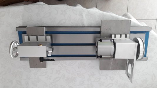
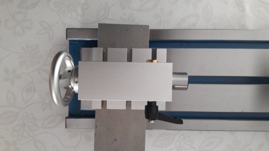
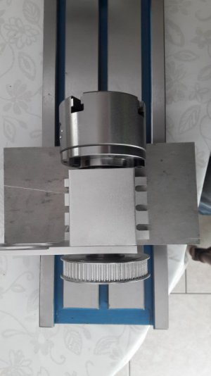
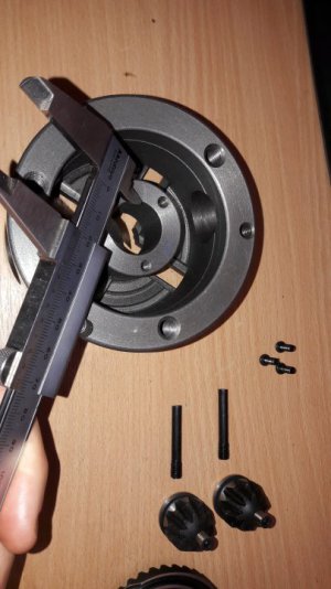
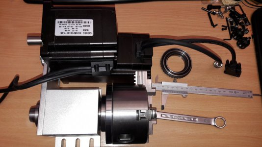
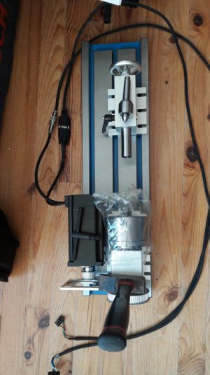
Dimension of the chuck : San Ou Zhejiang K12-100 mm, with 4 self-centering jaws, rated @3500 rpm max - tailstock Morse Taper #2, translation : 50 mm stroke.
Reduction ratio of 4 turns for the stepper motor, 1 turn in the spindle/chuck, transmission via a synchronous belt of 15 mm wide, 5 mm modulus, type HTD-405-5M. 405 stands for the peripheric length of this belt : 405 mm.

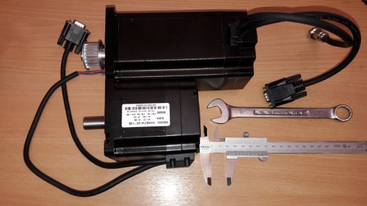
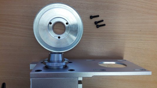
The stepper motor can be mounted on a junction plate linked to the spindle.
Some CNC 4th axis kits are sold with NEMA23 motors,
Sometimes NEMA24 motors could exist (havent meet them, yet).
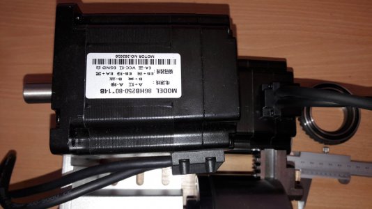
I have chosen the NEMA34 size.

The technology of the motor is a hybrid stepper motor, delivered with a high-voltage driver, rated @80 Volts DC; reading the rotor position via an embedded encoder, rated at 1,000 points per each turn; dialog with dual phase quadrature signals.


I have ordered some individual components, for building a lathe mixed with a mill. It is a melange. Maybe a spiced melange haha ^^

I need to do some basic operations on small axis parts, with grinding bench and some turning with carbide tools. Water & soluble oil cooling could be helpful.

I am not having yet a given machine-tool in my workshop, except a drill press.

I am building a quite decent workshop from the very beginning, for installing in some months a quite heavy machine, available in Europe : BF46 bench mill, available in Germany, Switzerland, Netherlands, France, Belgium... A "heavy" mill, like a BF-46 from Optimum Machines is given at 500 kilograms... I need to prepare the delivery.

But because of the impossibility to install heavy equipments yet, I am looking for lighter solutions, about turning & grinding.

One path which could be a way is a 4th axis kit, available for not too much money.

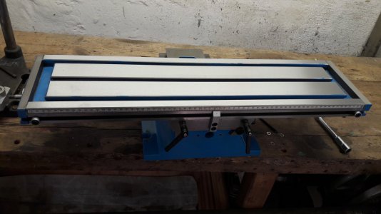
I have purchased a cross table, it is made from Chinese cast iron; the dimensions of the table are 700 mm x 180 mm (27.5" x 7" 1/8).
The 3 T-slots are spaced with 2.5" gap (63.5 mm); even for us which are using metric.

These cross tables are the same than mills which are available at PrecisionMatthews, like PM-25-MV mills.

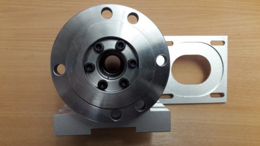
On this cross table, the idea is to place at the left corner the 4th axis block, on the opposite side the tailstock with a Morse Taper #2.
Both components are at the heigth of 65 mm.

But

With a space between the 3 T-slots of 2,5", it is impossible to align the 2 components on this cross table : they are not build with the same gap between bolts !!

So, I need to build two spacers/soles : one for the 4th axis spindle, the second for the MT#2 tailstock, with 2 precision-grinded, hardened pins, to ensure alignment on each spacer/sole.

The opening of the T-slots guideways of the cross table are 12,00 +/- 0.02 mm, very precise machining, good flatness and overall looking.
The expected heigth of these spacers / soles should be around 20,00 mm or 25,00 mm each, for gaining overall axis's heigth.

The material used for this project could be :
- French Afnor "AU4G" / EuroNorm AW-AlCu4MgSi / ASTM 2017A / Duralumin(tm) / German Werkstoff Nummer 3.1325
or
- French Afnor "Z160CDV12" / EuroNorm X155 CrMoV 12-1-1 / AISI P2 / German Werkstoff Nummer 1.2379.
I prefer to use the stainless steel, to avoid any galvanic-induced corrosion effect by using liquid with different materials.

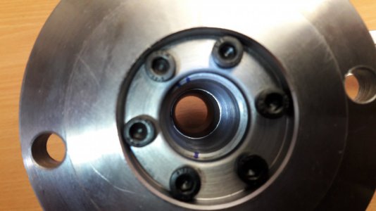
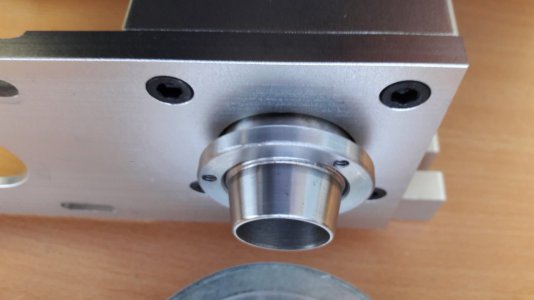
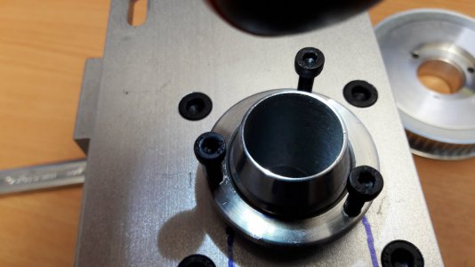
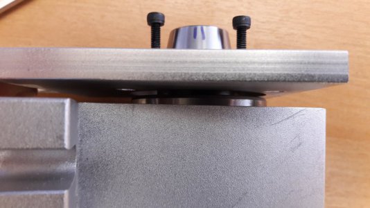
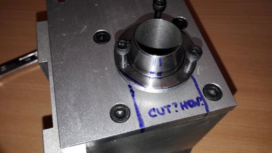
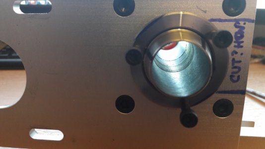
Please find attached some pictures of the setup.
 

Attachments

  • 20210507_180017.jpg
    20210507_180017.jpg
    148.1 KB · Views: 24
  • 20210804_093942.jpg
    20210804_093942.jpg
    61.7 KB · Views: 23
Last edited:
CyChtiZen, that is really interesting, and I see that there are a number of variations on the 4th axis rotators. And indeed, the prices are very compelling. I want one, now what would I do with it? What a dilemma. :)

And welcome!
 
Thanks for your wishes Winegrower !
This component can be very helful, allowing parts of diameter up to 21.9 mm (maybe 22,2 mm, let's be maaaad) to pass through the chuck and spindle's body.

Especially useful for laser marking, small tube works for bicycle's frames, little ironworks, cutlery operations prior or after die-forging, small CNC machining with full 4-axis machining, integration in a future cradle for 5-axis machining...

Lots, lots of possibilities...


The issue with the spindle block is as follows :

I need mechanical power : if I want to obtain chips, by turning the parts with this small-n-cheap 4-axis component.
The delivered stepper motor with this kit is a "small" NEMA34, hybrid stepper, able to reach 4 N.m of torque, metric style for shaft-n-keyway.

I have chosen a much more powerful hybrid stepper motor, delivered with a modern, closed-loop driver, which uses Digital Signal Processor, for producing several thousands periods of fine-adjusted currents into the coils, ensuring power, no loss of steps, but with low torque as hi-speed.

BUT

You can adapt later a servomotor build into a NEMA34 chassis, imperial or metric style, able to reach decent 750 watts of final power, able to accelerate/decelerate badly, some of them can reach 20 N.m of torque !
Some servomotors made by Delta Electronics, Yaskawa, Schneider, Siemens can reach up to 2 kW of pure power... yield is close to 98%.
Some servos can be ordered with a 24 VDC brake...

The result is actually : this long NEMA34 hybrid stepper motor is able to reach 3,500 rpm, rated @450 watts of power.

But,
  • Because of the reducing ratio of 4:1 or 3:1; it's not feasible to use the 4th axis spindle as a lathe, especially with small diameter parts which demands tremendous speeds. So I need badly a new pulley/wheel; and a corresponding belt with correct length.
And,
  • The NEMA34, rated at 12,0 N.m of torque is soooo long ...that the optical encoder is too close of the chuck's jaws; with a risk of collision of jaws with this precision optical encoder... See picture attached of the chuck's jaw colliding the encoder box.

So the junction plate of the NEMA34's motors needs to be replaced with a new design.
I have 2 possibilities :

1. to space much more the motor's axis from the spindle axis, thus lenghtening the belt. But the turnings, chips and debris will ruin quickly the painted body of the motor and its optical encoder housing; making the cleaning of area harsh, rusty and nasty.

2. to send the NEMA34 stepper motor on the opposite side, for giving space free to the chip production area, thus allowing the belt to be protected from them, via a sheet metal housing. But the torsionnal effort on a poor 10 mm-thick aluminium plate demand a much more, specially designed plate, able to convey the tensionned belt.

In both cases, the junction plate need to be removed. Or maybe reinforced with pins/spacers ? But the pulley is too big for obtaining a reducing ratio of 1:1 : the pin legs cannot be installed, the pulley is too big.

Because I wish :
- to use modern tool holders made of coated tungsten carbide, for reducing the need of power for making chips and coily turnings, and thus aiming a very good surface status,
- I need to reach quite fast turning speeds (2,800 to 3,600 rpm), especially when cutting with carbide tools MGEH/R or MGEH/Lxxx inserts : the more you go close to the center, the more you need to turn quickly...

Maybe the Chinese have placed into this spindle body some good quality bearings, able to provide some high speeds without failing.
...but maybe not. See the purchased price !

Because Chinese are using metric system, the interchangeability of metric-based generic bearings are MUCH MORE easy to be done with hi-grade bearings made in Sweden, Germany, Japan, Korea, France too. Thus allowing to suppress any play, vibrations, heating of this low-cost spindle.

Making more energy savings for chips and turnings.


See the pictures attached.
 

Attachments

  • 20210810_142637.jpg
    20210810_142637.jpg
    92 KB · Views: 14
  • 20210810_142644.jpg
    20210810_142644.jpg
    85.7 KB · Views: 9
  • 20210810_142657.jpg
    20210810_142657.jpg
    36.5 KB · Views: 9
  • 20211229_155040.jpg
    20211229_155040.jpg
    59.5 KB · Views: 9
  • 20211229_155816.jpg
    20211229_155816.jpg
    154.5 KB · Views: 7
  • 20211229_155834.jpg
    20211229_155834.jpg
    132.2 KB · Views: 7
  • 20211229_160209.jpg
    20211229_160209.jpg
    147.1 KB · Views: 6
Last edited:
The issue is : it is quite difficult to remove the junction plate, because this 10 mm-thick aluminium plate is trapped between the aluminium body of the spindle, and the aluminium alloy hollow axis's flange. The plate cannot be removed, without

  1. - cutting the 10 mm thickness of the junction plate, with a jeweler saw or carbide hacksaw, with few space for the blade : almost 5 mm to do so...
  2. - unscrewing the half of the hollow axis, by applying a torque, BUT I have no way to apply the dismantling torque onto the round axis...

I need to unscrew the hollow axis itself, prior of removing the plate. It could be a way to check the bearings.
...And I don't have any surface able to withstand the unscrew torque.

The axis's connecting flange to the synchronous wheel is made with only 3 tapered holes, for M4 screws. If I insist by using the aluminium wheel as a lever, it exist a risk of destroying the 3 screws with excessive torsion/scissoring forces.

I have several options, that's why I am sending this message, prior to do irreversible decisions and mistakes.

  1. First one is the send the spindle body into a fridge and cooling it @-25°C; then trying to unscrew with some keys and the rubber belt, to avoid any scratch on the tapered precision cone which helds and centers the 99 mm diameter pulley.
  2. Second one is to use a gentle flame or oven's heat for removing an hypothetical glue, but the thread is very clean, no trace of Loctite's glue is visible here.
  3. Third solution could consist to grind/filing two flat, parallel surfaces onto the shoulder's flange, for allowing a parallel wrench to manoeuver the axis.
Is someone here has already teared down a 4th axis block without making huge mistake ??

What could be the best approach to do better, not worse ?
 

Attachments

  • 20211229_160333.jpg
    20211229_160333.jpg
    107.7 KB · Views: 6
  • 20211229_160414.jpg
    20211229_160414.jpg
    87.5 KB · Views: 7
  • 20211229_160630.jpg
    20211229_160630.jpg
    139.8 KB · Views: 8
  • 20211229_160650.jpg
    20211229_160650.jpg
    80.6 KB · Views: 9
Last edited:
How a fourth axis spindle is built ???
How I can dismount / tear down it ?

By having a carefully inspection of the hollow shaft aspect, see clearly 3 distinctive parts, which seems to be assembled via 2 threads, in the middle of the aluminium block body.

The rear (pulley) side seems to have a nice fine threading; no traces of glue is visible, either on the visible side nor inside the hollow shaft. The internal thread is at 43 mm below the neck of tapered flange.

The front side seems to be also threaded, the junction is well inside the block. The Mitutoyo caliper indicate a depth of 61 mm, from the reference of the flange/chuck inferior face.

The 3 internal parts which constitues the internal bore are made by 3 different setting of internal bore machining; see the 4th pictures where the ligth illuminate clearly the 3 internal machined surfaces.

Please find attached the blue marking of possibilities :

- Creating 2 parallel surfaces for unscrewing with an adjustable wrench (10 to 12" long, or maybe longer). Doing so at room temperature ?
- Doing the unscrewing effort at low temperature, because of the retractation of metals, maybe with some drops of WD-40 prior to freezing,
- Doing the unscrewing effort at mid-temperature via an oven, @130°C to 150°C, for soften a montage glueing.
- Cutting the plate with a thin, reciprocating blade, via 2 grooves which will be very difficult to obtain.

After a first try with light pliers wrapped around an old belt (to avoid any scratches onto the tapered aluminium neck), the two blue ink marking has shown no movement accomplished.

Best regards !
 

Attachments

  • 20211229_193928.jpg
    20211229_193928.jpg
    110.8 KB · Views: 6
  • 20211229_194507.jpg
    20211229_194507.jpg
    157.2 KB · Views: 4
  • 20211229_194816.jpg
    20211229_194816.jpg
    177 KB · Views: 4
  • 20211229_201501.jpg
    20211229_201501.jpg
    96.3 KB · Views: 8
If there is reduction gearing in there, high speeds will probably destroy it pretty quick. It's not designed for that. Maybe better to build a straight lathe type headstock for high speed use.
 
For the need of a fourth axis, the machining technique needs small and slow movements, not too much backlash; and lots of torque for "holding" the part under the pressure made by the cutting tool. With a reduction of 4:1; with the equipped hybrid stepper motor, I should obtain 4 x 4 N.m; which is ...adapted to small scale operations.

Effectively, for a lathe, the belt should be larger in order to carry higher mechanical energy. I think that the 2 or 3 contained bearings should easily withstand the mechanical energy applied.

I have seen a Duplomatic automatic turret (or carousel ? dunno the exact term used in UK/US) used for modern CNC-lathes. Some of them are containing 4, 8, 12, 16 tools. But some industrial Duplomatic turrets holds micro-motors, helpful for some C-axis machining, with 2 kW of embedded power. Lots of drills, tapers can be mounted onto these powered and sometimes able to withstand with cutting coolant fluid circuitry extensions.

If the bearings are killed, I hope to replace them easily. Transforming a mill towards a "machining center" is a very helpful advancement.

I have seen the price of some lathes sold equipped with a translational mill; we are close to 3,300 €.
...for a toy, using small cutting bars of 12x12 mm with brazed carbide.

...Like Qui Gon-Jinn said in StarWars episode I : "If you bet, always be prepared to loose".

At worse, it will be a set of bearings ^^ It should worth it :p
 

Attachments

  • Tour-CNC-2-3-4-axes-mono-et-bi-broche-horizontal-ROMI-Serie-G-550-550M-4.jpg
    Tour-CNC-2-3-4-axes-mono-et-bi-broche-horizontal-ROMI-Serie-G-550-550M-4.jpg
    126.9 KB · Views: 9
Last edited:
Welcome to H-M.
Quite interesting. I will definitely be following your build!
 
Removing the rear flange nut is an interesting problem.

I think what I would do is put the chuck back on the spindle to add mass to the spindle, then screw one of the bolts into the flange nut. Then using a soft punch (aluminum bar?) and a hammer, loosen the nut using the impact method. Place the punch as close to the nut as possible. This should not damage anything and may be the most effective way of loosening the nut.
 
Back
Top