- Joined
- Sep 22, 2010
- Messages
- 7,223
A Quick Change Toolpost
By John Stevenson
--------------------------------------------------------------------------------
In production engineering anything that can save time or an operation also saves money. In model engineering it does not apply as rigidly but where it can be applied it can pay dividends in time. We all use these shortcuts whether we realise it or not. Using one item to drill another one from is jig drilling, a common production practise.
When a few years ago I made the transition from playing to working I looked at ways to speed up simple jobs on the lathe, especially one off jobs that cannot be set up for production i.e. just about every thing that the model engineer does. One of the first things that I looked at was the toolpost and tool setting. As my Myford lathe had a single bolt toolpost and my others had four turret posts I was able to compare them well. The single bolt toolpost had the one main disadvantage of having to change tools and set up every time. The Myford floating boat idea is a good one but limited to Myford tools. The four turret tool post has obvious advantages but it also has a few disadvantages, often when doing internal work i.e. boring and internal screw cutting you are often limited to only two tools to avoid fouling either the chuck or any tail stock operations that may be in use. Another disadvantage on the Myford is that only 3/8" square tools may be used because of room available. Any resharpening done on either set-up requires the tool to be repacked to its correct centre height.
This led me to look at the idea of a quick change tooling system where the tools are always set in a holder and if any adjustment or change is to be made it can be done easily. Two main disadvantages are obvious to this system,
[1] The cost, these commercial tool holders are expensive and are probably beyond the reach of many.
[2] They usually only come with three or four tool holders one of which is usually a boring tool holder which limits the use of them to about the same as a four turret post.
When I studied the design of these toolposts I came to the conclusion that they were more complex that they needed to be. In fact the toolholder was more complex than the block. Only one block has to be made, whereas many holders are required so it is obvious that the holder requires to be as simple as possible. On my small toolholder for the Myford I have 14 holders, to some people that may be over the top but it allows me to keep complete set-ups, also most of these were made by my 14 year old son.
The toolholder can be itemised into 4 main parts:
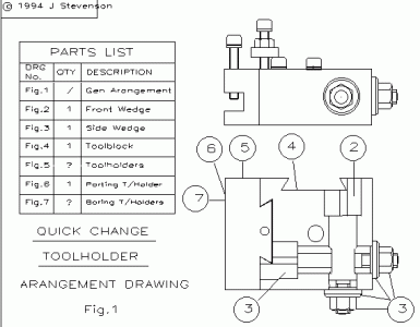
Figure 1 - Toolholder
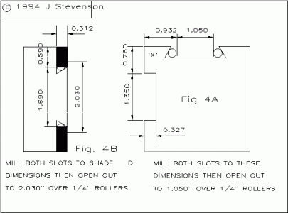
The Toolblock Figs, 4, 4a, 4b,
The Front Wedge Fig , 2,
The Side Wedge Fig , 3,
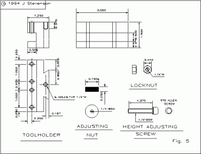
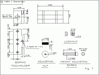
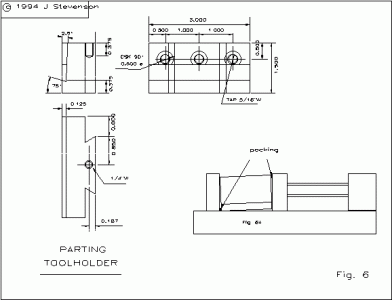
The Toolholders Figs, 5, 6, 7,
Various small parts nuts e.t.c. are incorporated on the related drawings.
The principle of operation is that in the block there are two wedges that have a dovetail machined on their ends, these are able to slide in a machined housing in the block but are prevented from rotation by two locating screws "A". When the toolholder which has been assembled with a height screw, adjusting nut and locknut, it is located in the slot and lowered to a preset height onto the stop screw head "B" and the wedge nut tightened. To change tool all that is required is to undo the wedge nut, tap it on its end and lift the holder clear.
In the design the Toolholder has been designed for a Myford or a lathe of similar size however there is no reason why the dimensions cannot be scaled to fit another machine. In fact I have 3 lathes all having this type of tool post the largest being a TOS of 12" centre height with 1" square tools and I have had no trouble at all.
If anybody wants to simplify the design there is no reason why one of the dovetail slots and a wedge cannot be left out of the design. It just means that you have to rotate the block to use internal tools.
To allow parts to be used as jigs the wedges will be described first.
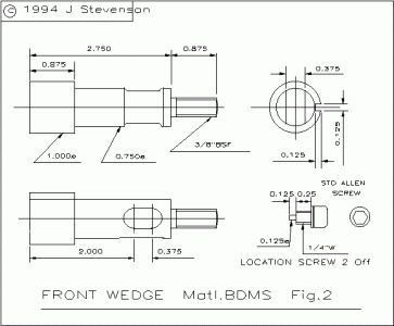
Figure 2 - Front Wedge
This is made out of a piece of 1"dia. BDMS. 3,5/8" long. The front and side wedges are very similar except where one passes through the other. Face to length and centre one end. Grip by 3/4" in the chuck and turn down to 3/4"dia. for 2,3/4", then turn down the last 7/8" to 3/8"dia and thread it 3/8 BSF. Remove from chuck and replace with side wedge.
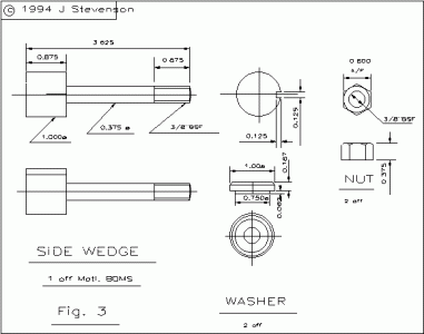
Figure 3 - Side Wedge
This is made out of the same material as the front wedge and turned the same only turn down to 3/8" for the whole 2 3/4" and thread 3/8 BSF. When both wedges are machined transfer them to the milling machine and mill a 1/8" wide x 1/8" deep slot on the 1" dia. for the whole length of 7/8". The side wedge is now completed, clamp the front wedge in the vice with the 1/8" slot 90 degrees at the side, mill a 3/8" slot 2" from the large end for a length of 3/8". Check to see if the side wedge will pass through.
Two nuts and washers are required for the wedges. The washers are straightforward turning jobs and the nuts can be commercial nuts or made to fit your favourite spanner.
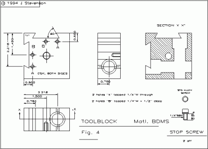
Figure 4 - Toolblock
The Toolblock is made from a piece of 3" x 3" x 1 1/2" BDMS. Grip in the four jaw chuck and face all sizes. Set to run true and centre and drill the 7/16" centre hole [Myford only, check your lathe]. Remove from lathe and blue up, [I use a 1/2" wide Edding 600 blue marker pen, it's quicker and less messy]. Mark out front wedge and side wedge holes also the 4 top holes. Set up in the four jaw chuck with the front wedge hole running true, centre and drill out to just under 3/4 " bore to 3/4". Open out to 1" dia. for 1" long, try the front wedge for a sliding fit. Turn round in chuck and repeat for side wedge hole. Remove from chuck and drill and tap top holes. Holes "A" need to be tapped through and holes "B" need be 1/2" deep. Make the two locating screws next, these can be made or commercial screws cut down, I used allen screws. When tightened they are required to locate in the slots on the wedges, not to lock them. Two items are now required that are not on the drawings, these are washers 1"dia o/d. x 3/4"dia i./d x 1/8" thick. These go under the heads of the wedges to bring them to the surface of the block, install these washers, wedges and fit the washers and nuts. Make sure the locating screws are fitted. Set up in the miller, front wedge uppermost and mill the slot to the dimensions in Figure 4A with all measurements taken from the front corner 'X'. Change the cutter for a 60 degree dovetail cutter and mill the sides out to the dimensions in Fig. 4A over two 1/4" rollers. Remove the sharp edge to provide clearance at the bottom of the holder. Rotate and repeat for the side wedge remembering to measure from corner 'X'. When I made my second block I clamped a piece of 1/8" thick plate to the block before milling the slots, after milling this gave me a test gauge for testing the holders.
The dimension of 1.050" can be plus .010", minus .000" try to keep to this. If you get a holder with a large clearance it will still work because it still pushes onto the front fixed dovetail slide.
Figure 5 - Toolholder
This is made from a piece of 1 1/4" x 1 1/2" x 3" long BDMS. It is a good idea at this time to work out at this time how many toolholders are required, and what type, as they can be machined as a job lot or as I do with a lot of ongoing jobs, I pick them up and put them down again as I have the time or as machines are set for other jobs. There are three types of toolholder, one of which, the parting toolholder, you will only require one off. This leaves us with normal and boring tool holders as shown in Figs. 5 & 7. The use of normal toolholders requires no description here but a note on the use of quick change boring toolholders. Because boring tools are usually short on the shank [ as opposed to boring bars], it is perfectly allowable to bore either end of the holder to a different diameter to suit different tools. These can be made use of by drilling and tapping the clamp screws through and drilling and tapping an extra height screw hole on the bottom face. This also allows you to use these holders on the side position with round tools, [ I often use mine for slotting screw heads with a slitting saw in the chuck ]. Set the holder in the milling machine and mill out the slots to the shaded dimensions in Fig . 4B. Mill all the holders at these settings. Change the cutter for the dovetail cutter and mill the slots out to 2.030" across two 1/4" rollers. Test with the block or gauge for an easy fit. Turn over in the miller and mill the tool slot, if 1/2" wide tools are required to be used increase the slot to 9/16". Remove from the miller, mark out and drill and tap the five top holes. The hole for the height screw only requires tapping with a taper tap to allow the screw to wedge in the hole. The clamp screws can be anything to hand but if you have to purchase anything then allen screws make a satisfactory job of it.
Figure 7 - Boring Toolholder
These are made in exactly the same way and at the same time as the normal toolholders. The difference comes when putting the hole in for the boring tool. Assemble the complete toolholder and fit it onto the lathe. Square the block up by holding it up to the face plate or a parallel bar in the chuck and tighten up. Fit the boring toolholder on in mid height position and lock. Wind the crosslide in to the centre line and grip a centre drill in the three jaw chuck, centre and drill through. To stop the block attempting to twist push the toolholder with the tail stock. If two different diameters are required turn the block over, line up with the drill in situ and redrill to the larger size.
Figure 6 - Parting Toolholder
This is a special holder and needs to be made only if you use parting tool blades as opposed to square tools ground up to shape. These blades can be obtained in various sizes so make sure you have a stock before starting and amend the tool dimensions on the holder drawing if necessary. There is nothing more infuriating than to make a toolholder and then find out the blades or tips are obsolete! these inserts are uaually stocked in 5/16",1/2",3/4" sizes.
The holder is made from a piece of 1 1/2" x 1" BDMS steel 3" long. Face to length and mill slots and dovetail as previous holders. Turn over in the vice with the dovetail at the bottom and clamp across the 1 1/2" width with two narrow pieces of packing 1/8"wide x 3"long x 0.040" thick at either side. The strips need to be at the bottom of the bottom face and the top of the top face as in Fig. 6A. This will tilt the block 2 1/2 degrees for side clearance on the tool as most parting tool blades are ground with a total clearance of 5 degrees. This operation is for people without a swivel head miller or tilting vice, however if you have one it is still quicker than moving and then reclocking square. Mill the slot to depth and width so that the blade nearly slides in. Change the cutter for an old or broken slot drill. Grind one flute back for clearance and grind the other to 15 degrees to suit to bottom edge on the blade and back off for clearance.
This sounds very crude but for a one off job it is also very effective.
Mill the bottom edge of the slot out until the tool is a nice slide fit.
Remove from miller and blue up. Lay three 5/16" countersunk head allen screws upside down with the head o f the screw 1/3 over the blade, mark out, drill tap and countersink lightly. try the blade and aim to get the screw to touch the blade just before it grips the holder.
To allow 1/2" square tools to be used the corners have to be removed from the top slide as in Photo. 1. This is actually a special top slide that I made to cut longer tapers and is equipped with the screw and nut from a cross slide. If however you don't want to modify your machine you will have to stay with 3/8" square tools.
 View attachment 102120
By John Stevenson
--------------------------------------------------------------------------------
In production engineering anything that can save time or an operation also saves money. In model engineering it does not apply as rigidly but where it can be applied it can pay dividends in time. We all use these shortcuts whether we realise it or not. Using one item to drill another one from is jig drilling, a common production practise.
When a few years ago I made the transition from playing to working I looked at ways to speed up simple jobs on the lathe, especially one off jobs that cannot be set up for production i.e. just about every thing that the model engineer does. One of the first things that I looked at was the toolpost and tool setting. As my Myford lathe had a single bolt toolpost and my others had four turret posts I was able to compare them well. The single bolt toolpost had the one main disadvantage of having to change tools and set up every time. The Myford floating boat idea is a good one but limited to Myford tools. The four turret tool post has obvious advantages but it also has a few disadvantages, often when doing internal work i.e. boring and internal screw cutting you are often limited to only two tools to avoid fouling either the chuck or any tail stock operations that may be in use. Another disadvantage on the Myford is that only 3/8" square tools may be used because of room available. Any resharpening done on either set-up requires the tool to be repacked to its correct centre height.
This led me to look at the idea of a quick change tooling system where the tools are always set in a holder and if any adjustment or change is to be made it can be done easily. Two main disadvantages are obvious to this system,
[1] The cost, these commercial tool holders are expensive and are probably beyond the reach of many.
[2] They usually only come with three or four tool holders one of which is usually a boring tool holder which limits the use of them to about the same as a four turret post.
When I studied the design of these toolposts I came to the conclusion that they were more complex that they needed to be. In fact the toolholder was more complex than the block. Only one block has to be made, whereas many holders are required so it is obvious that the holder requires to be as simple as possible. On my small toolholder for the Myford I have 14 holders, to some people that may be over the top but it allows me to keep complete set-ups, also most of these were made by my 14 year old son.
The toolholder can be itemised into 4 main parts:
Figure 1 - Toolholder
The Toolblock Figs, 4, 4a, 4b,
The Front Wedge Fig , 2,
The Side Wedge Fig , 3,
The Toolholders Figs, 5, 6, 7,
Various small parts nuts e.t.c. are incorporated on the related drawings.
The principle of operation is that in the block there are two wedges that have a dovetail machined on their ends, these are able to slide in a machined housing in the block but are prevented from rotation by two locating screws "A". When the toolholder which has been assembled with a height screw, adjusting nut and locknut, it is located in the slot and lowered to a preset height onto the stop screw head "B" and the wedge nut tightened. To change tool all that is required is to undo the wedge nut, tap it on its end and lift the holder clear.
In the design the Toolholder has been designed for a Myford or a lathe of similar size however there is no reason why the dimensions cannot be scaled to fit another machine. In fact I have 3 lathes all having this type of tool post the largest being a TOS of 12" centre height with 1" square tools and I have had no trouble at all.
If anybody wants to simplify the design there is no reason why one of the dovetail slots and a wedge cannot be left out of the design. It just means that you have to rotate the block to use internal tools.
To allow parts to be used as jigs the wedges will be described first.
Figure 2 - Front Wedge
This is made out of a piece of 1"dia. BDMS. 3,5/8" long. The front and side wedges are very similar except where one passes through the other. Face to length and centre one end. Grip by 3/4" in the chuck and turn down to 3/4"dia. for 2,3/4", then turn down the last 7/8" to 3/8"dia and thread it 3/8 BSF. Remove from chuck and replace with side wedge.
Figure 3 - Side Wedge
This is made out of the same material as the front wedge and turned the same only turn down to 3/8" for the whole 2 3/4" and thread 3/8 BSF. When both wedges are machined transfer them to the milling machine and mill a 1/8" wide x 1/8" deep slot on the 1" dia. for the whole length of 7/8". The side wedge is now completed, clamp the front wedge in the vice with the 1/8" slot 90 degrees at the side, mill a 3/8" slot 2" from the large end for a length of 3/8". Check to see if the side wedge will pass through.
Two nuts and washers are required for the wedges. The washers are straightforward turning jobs and the nuts can be commercial nuts or made to fit your favourite spanner.
Figure 4 - Toolblock
The Toolblock is made from a piece of 3" x 3" x 1 1/2" BDMS. Grip in the four jaw chuck and face all sizes. Set to run true and centre and drill the 7/16" centre hole [Myford only, check your lathe]. Remove from lathe and blue up, [I use a 1/2" wide Edding 600 blue marker pen, it's quicker and less messy]. Mark out front wedge and side wedge holes also the 4 top holes. Set up in the four jaw chuck with the front wedge hole running true, centre and drill out to just under 3/4 " bore to 3/4". Open out to 1" dia. for 1" long, try the front wedge for a sliding fit. Turn round in chuck and repeat for side wedge hole. Remove from chuck and drill and tap top holes. Holes "A" need to be tapped through and holes "B" need be 1/2" deep. Make the two locating screws next, these can be made or commercial screws cut down, I used allen screws. When tightened they are required to locate in the slots on the wedges, not to lock them. Two items are now required that are not on the drawings, these are washers 1"dia o/d. x 3/4"dia i./d x 1/8" thick. These go under the heads of the wedges to bring them to the surface of the block, install these washers, wedges and fit the washers and nuts. Make sure the locating screws are fitted. Set up in the miller, front wedge uppermost and mill the slot to the dimensions in Figure 4A with all measurements taken from the front corner 'X'. Change the cutter for a 60 degree dovetail cutter and mill the sides out to the dimensions in Fig. 4A over two 1/4" rollers. Remove the sharp edge to provide clearance at the bottom of the holder. Rotate and repeat for the side wedge remembering to measure from corner 'X'. When I made my second block I clamped a piece of 1/8" thick plate to the block before milling the slots, after milling this gave me a test gauge for testing the holders.
The dimension of 1.050" can be plus .010", minus .000" try to keep to this. If you get a holder with a large clearance it will still work because it still pushes onto the front fixed dovetail slide.
Figure 5 - Toolholder
This is made from a piece of 1 1/4" x 1 1/2" x 3" long BDMS. It is a good idea at this time to work out at this time how many toolholders are required, and what type, as they can be machined as a job lot or as I do with a lot of ongoing jobs, I pick them up and put them down again as I have the time or as machines are set for other jobs. There are three types of toolholder, one of which, the parting toolholder, you will only require one off. This leaves us with normal and boring tool holders as shown in Figs. 5 & 7. The use of normal toolholders requires no description here but a note on the use of quick change boring toolholders. Because boring tools are usually short on the shank [ as opposed to boring bars], it is perfectly allowable to bore either end of the holder to a different diameter to suit different tools. These can be made use of by drilling and tapping the clamp screws through and drilling and tapping an extra height screw hole on the bottom face. This also allows you to use these holders on the side position with round tools, [ I often use mine for slotting screw heads with a slitting saw in the chuck ]. Set the holder in the milling machine and mill out the slots to the shaded dimensions in Fig . 4B. Mill all the holders at these settings. Change the cutter for the dovetail cutter and mill the slots out to 2.030" across two 1/4" rollers. Test with the block or gauge for an easy fit. Turn over in the miller and mill the tool slot, if 1/2" wide tools are required to be used increase the slot to 9/16". Remove from the miller, mark out and drill and tap the five top holes. The hole for the height screw only requires tapping with a taper tap to allow the screw to wedge in the hole. The clamp screws can be anything to hand but if you have to purchase anything then allen screws make a satisfactory job of it.
Figure 7 - Boring Toolholder
These are made in exactly the same way and at the same time as the normal toolholders. The difference comes when putting the hole in for the boring tool. Assemble the complete toolholder and fit it onto the lathe. Square the block up by holding it up to the face plate or a parallel bar in the chuck and tighten up. Fit the boring toolholder on in mid height position and lock. Wind the crosslide in to the centre line and grip a centre drill in the three jaw chuck, centre and drill through. To stop the block attempting to twist push the toolholder with the tail stock. If two different diameters are required turn the block over, line up with the drill in situ and redrill to the larger size.
Figure 6 - Parting Toolholder
This is a special holder and needs to be made only if you use parting tool blades as opposed to square tools ground up to shape. These blades can be obtained in various sizes so make sure you have a stock before starting and amend the tool dimensions on the holder drawing if necessary. There is nothing more infuriating than to make a toolholder and then find out the blades or tips are obsolete! these inserts are uaually stocked in 5/16",1/2",3/4" sizes.
The holder is made from a piece of 1 1/2" x 1" BDMS steel 3" long. Face to length and mill slots and dovetail as previous holders. Turn over in the vice with the dovetail at the bottom and clamp across the 1 1/2" width with two narrow pieces of packing 1/8"wide x 3"long x 0.040" thick at either side. The strips need to be at the bottom of the bottom face and the top of the top face as in Fig. 6A. This will tilt the block 2 1/2 degrees for side clearance on the tool as most parting tool blades are ground with a total clearance of 5 degrees. This operation is for people without a swivel head miller or tilting vice, however if you have one it is still quicker than moving and then reclocking square. Mill the slot to depth and width so that the blade nearly slides in. Change the cutter for an old or broken slot drill. Grind one flute back for clearance and grind the other to 15 degrees to suit to bottom edge on the blade and back off for clearance.
This sounds very crude but for a one off job it is also very effective.
Mill the bottom edge of the slot out until the tool is a nice slide fit.
Remove from miller and blue up. Lay three 5/16" countersunk head allen screws upside down with the head o f the screw 1/3 over the blade, mark out, drill tap and countersink lightly. try the blade and aim to get the screw to touch the blade just before it grips the holder.
To allow 1/2" square tools to be used the corners have to be removed from the top slide as in Photo. 1. This is actually a special top slide that I made to cut longer tapers and is equipped with the screw and nut from a cross slide. If however you don't want to modify your machine you will have to stay with 3/8" square tools.


 View attachment 102120
Last edited by a moderator:

