Hi
@BlueDeuce
That brand is mostly known for driving pellet stove feeders. Your motor may be for something else, because it is a 1.5HP size.
The the windings are normally changed from 115V operation to 230V operation by connecting then in either a parallel, or a series configuration.
Also, it is reversible, so there may be winding tappings that go to a reversing switch
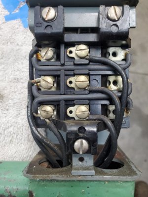
I can usually figure out the scheme from the winding terminal numbers, and a connection diagram, such as shown in your picture.
A little instinct + logic can let it start to make sense. For example, windings are often numbered such that one can reasonable guess that there is copper between a "1" and a "2".
I am called away soon, so I can't help untangle this right now, but we have had a previous new member thread which, if followed to its end, yielded a whole lot about motor connections, low voltage, high voltage, reversing, etc.
Very useful diagrams and advice were provided by
@markba633csi , who has seen a lot of these.
Mark, if he is around, may be able to help.
-->
Advice thread Motor Connections Discussion
Near the end of page 3, and a little into page 4
We can see the three terminals that do not have screws in them. These are presumably the ones that go to the motor.
It would help a lot to establish which terminals the incoming mains power cables arrive at on the switch.


.jpg")