There was another thread I had started to discuss the possibility of building a dividing head. Well, I decided to proceed. As many know, I like to build my own tooling and try to show the home hobby machinist how to make decent quality tooling without the big cash outlay required to purchase it. This project is of that thinking. While most dividing heads use a 40:1 ratio worm gear set, it is way too costly to plunk down $150 to $250 for a new worm gear set. Sometimes they can be found reasonable on sites like ebay, but not often. I was researching how to drive a spur gear with a worm cut on the lathe as several dividing head projects do this and it will work well. The latest issue of Home Shop Machinist magazine has an article covering how to do just this, but it arrived too late for me as I got a nice 30:1 worm gear set donated to the project by a friend.
The first thing we are going to do is dispel the notion you must use a 40:1 ratio because most use it and the available plate charts use it. There are several ratios that have been used over the many years. Every manufacturer has proprietary plates because of their size, or the way they mount, or where they mount. I have been developing the holes patterns for the plates using the simple formula Harold Hall provides in his dividing head info on his web site, so my plates will work with my head and the 30:1 ratio. So the notion about having to have a special ratio is horse puckey !
The following formula is used to determine the holes required for a number of divisions. While the example uses 10 holes a larger multiple of holes will cover the same number of divisions and several more.
R = Ratio
H = Holes
D = Divisions
W = Holes per division ( must be a whole number and will be as long as it is a multiple of D)
W = R x H / by D
lets say we have a 30:1 ratio. 30 turns of the handle gives one turn of the spindle. We want to make a gear with 50 teeth or a graduated dial with 50 divisions. W must and will be a whole number as long as H is equal to or a multiple of 5 we can get the number of holes needed. 10 is a multiple of 5, so a plate with 10 holes , 3 x 10 = 30 ; divided by 5 = 6, so indexing every 6 holes will give you 50 divisions in one turn of the spindle. In other words, 6 holes times 50 divisions equals 300 holes. with a 10 hole plate, thirty turns of the handle equals 300 holes or 50 divisions.
This can be done to figure any divisions needed and is how I figured the holes pattern for the indexing plates.
Now with that done, lets get started with this project. While many of my projects have been done in a timely (slang for fast) manner, This project will take longer as due to recent developments my shop time is considerably less.
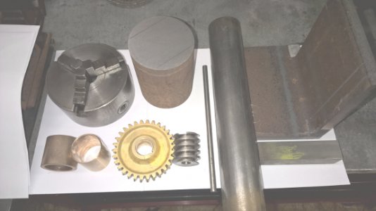
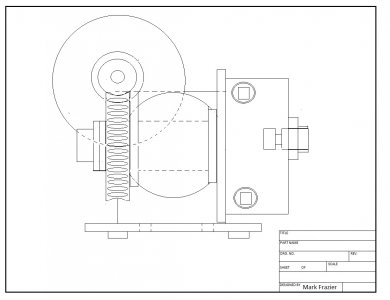
I have acquired a worm gear set and will now start to design the dividing head around it.( remember, in the absence of a worm gear set , you can cut a worm on many lathes to drive a spur gear such as a change gear).
First , I have a list of desired features wanted in this dividing head:
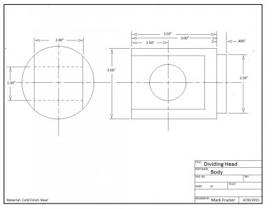
1. This will not be a big honking monster. I want it smaller to use on smaller machines such as the Burke mill.
2. I want to be able to disengage the worm for direct indexing if desired.
3. I want to be able to tilt 90 degrees to use vertically ( not sure I will get this one yet).
4. I want a threaded spindle to accept a chuck and also be able to use collets (wanted 5C, but will be using 3C due to spindle size).
5. Sector arms will probably not be made till needed.
I have some of the materials on hand for this project and will start posting photos tomorrow.
Last edited by a moderator:


