A Beginners Clock

B

BRIAN

Forum Guest
Register Today
Have you ever wanted to make a clock BUT came up with a list of problems like .
Cost of brass---cost of cutters--plans- dividing head---I havent the knowledge --ETC ETC.

Have you a lathe With very little accesories, and wonder what you can make.

In this project I will be using only my basic 7x12 as it came in the box--a small bench drill-- A Dremmel type mini drill. And the normal hand tools found in a shop.

If we need other tools we will make them, But we are not going to spend a lot of the green crinkly stuff.
:nono:
Many plans start with a simple clock design then try to make it on a lathe.
But I have turned this around, saying, what can I use on this lathe and drill, to make a clock.

The design of the gear train allows all the gears etc on this clock to be made by direct indexing from the 60t and 80t gears that come with the lathe
no fancy compound gearing to get the right tooth count.

The design will be based on Janes Clock but with a lot less brass, only the gears will be of brass.
the frames etc will be blued steel I expect the cost to be less than a 1/3 of Janes Clock

The first test gear has been made with a home made cutter so i am on my way!

I have just rememberd I havent compressed the photos so I will do another post with them in.
:nuts:

Brian.
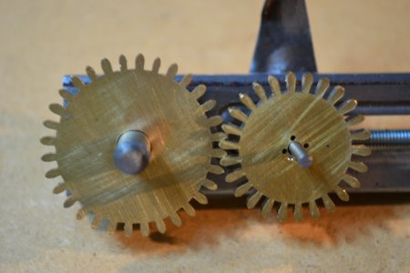
Immagine 016.jpg
 
Last edited by a moderator:
Re: The next project

Brian,

I would be interested in seeing how you made the cutter for the test gears.

Tom
 
Re: The next project

Hi Tom

I was rather thinking that this was the first question that was going to be asked.
well here it is.in all its simplisity


P1011796.JPG


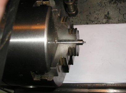
Using a tool ground to the correct radius turn down a piece of 1/4"silver steel until the tip is the same as the bottom of the cut,

P1011798.JPG


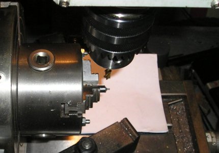
Halve it ,this can be done in the lathe with a fileing rest. harden and temper.

Immagine 013.jpg

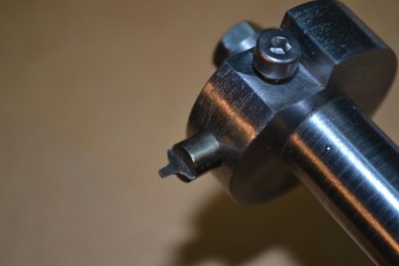
Use in a tool post milling attachment.( home made out of scrap )

In the photo of the 2 gears, the test one is on the right the other was cut on the mill with a commercial cutter

At this stage I still had a bit of work to do on the indexing on the lathe but I think it stands up quite well.

It certanly ran well against the other gear.

Brian.

P1011796.JPG P1011798.JPG Immagine 013.jpg
 
Re: The next project

Brian,

So you aren't generating a true cycloidal tooth profile, just a approximation. How did you decide what radius to use on the cutter for that particular gear?

Tom
 
Re: The next project

I mesured the existing cutter with a gauge.
My cutter fits the original gear perfectly so if its good enough for them its ok for me i reduced the length of the cutter to make the tip stronger, trad style teeth are very deep but this is not nessasary, more modern clocks have
shallow teeth or even rounded bottoms.
There is a program in M.E. utilities to find this radius if you dont have a cutter to copy.
One of my problems is to keep this project simple so a newbe can build it with little tooling and keep the cost down .
What you will see is a prototype, if i manage to make a clock that works and looks good I will make it into
a plan/book with lots of photos including the making of the cutters ,milling spindle, ETC .

Brian
 
Re: The next project

Thanks Brian.

I scoured the M.E. website for that program but was unsuccessful. Do you happen to have a link to it?

Tom
 
Re: The next project

Hi Tom
when H.M: had the first system it was in the downloads I think

anyway try www.alanjmonday.info he put it together.

For me the profile just has to work as it is running against lantern pinion trundles, simply round pins that do not even have to be of a particular size, just so long as they
fit between the teeth with enough clearance and are strong enough.
Dont confuse clockwork with top end enginering : That it is NOT.

Brian.
 
Re: The next project

Back again
also try

M:E:W:-----March/ april------1997-page52

Iam told this was a update. tho I have not seen it.
Let me know how you get on

if you cant get it I may be able to send you a copy of what i have.

Brian
 
Re: The next project

Brian,

As it turns out, I had the answer to my question all the time. My search of the M.E. website turned up an article by David Creed on making your own cycloidal cutters that referenced "Wheel and Pinion Cutting in Horology" by Malcom Wild. Duh! I added that book to my library last spring and never got around to reading it. It goes into great detail on making your own cutters, including all the different radii for any size wheel or pinion imaginable. If you don't have this book, you may want to check it out. It also mentions a device called the "Eureka continuous form relieving attachment" for reliving the form on multi-tooth cutters. It sounds like drawings may be available to make one, so the search continues...

Tom
 
Re: The next project

Thanks for the info Tom.

It just shows that it pays to read what you type .
In the photo of the two gears the test gear is on the LEFT. not as stated.
I must be getting daft. :nuts:

Brian
 
Back
Top