New member here..
I like making things from stuff that was never intended to be used in the manner in which I use them.
For instance, a few years ago a friend of mine had a issue with a lathe he bought. The lathe was 480 volts with no prevision to rewire the motor to 220 other than having an electrical shop re-wind it. I believe it had a Italian motor and it was going to cost quite a bit to rewind it.
I wondered if I could set up a rotary phase converter to produce 480 Volt 3 phase from 220 Volt single phase.
I found a 3450 RPM 5 hp 240/480 volt 3 phase motor in a salvage yard for $25. The same salvage yard had two large transformers with a 2X step up leg for $25 each also.
I spent a day at another salvage yard and covered the bed of my lwb truck with various 3 phase cutoff boxes, electronics enclosures, on / off switches, contacts, etc. I believe I paid 50 for the entire lot. I also salvaged large capacitors from many different air conditioning equipment and industrial machines while there.
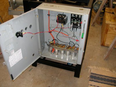
I set up the phase converter to be a push button start using the capacitors and a momentary contact pushbutton. The momentary button supplied the power to an electrical contactor, that when applied, connected one leg of the stepped up 480V to the dead leg of the motor using the capacitors to shift the phase for starting. Same principle as a static "phase converter" box. The pushbutton is held in while the main switch is thrown. It takes about a half second for the motor to reach full rpm, at which time you release the button, dropping the capacitors out and the motor continues to run on the two legs.
The transformers stepped up the 220V Single Phase to 480V Single Phase. I used one transformer per leg, for a total of two transformers. There was probably a more simple way, but this worked well.
Once the 480 Volt motor was running, it produced the third leg of the 3 phase power.
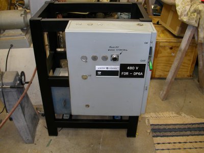
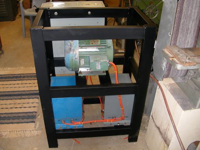
I have attached pictures of the set up and the frame I welded together to house it.
I liked the way this worked so well that I next set up my previous rope start rotary phase converter to a push button capacitive start as my next project.


