3phase Panel Wiring Question

Glenn Brooks

H-M Supporter - Gold Member
H-M Supporter Gold Member
Joined
Nov 14, 2014
Messages
851
Hi,

I've got a 10hp 3phase RPC driving my lathe. Recently I bought a three phase OD grinder, and have decided to run both machines through a Seimens PL power center (three phase panel) having a separate 3 Ph breaker for each machine.

Iam using standard US color coded wiring coming from the RPC panel to the breaker panel:

L1 - black
l2- red
l3 -blue
Neutral - green

However, I can't find any wiring schematic to indicate what the proper wiring configuration should be to connect the breakers to the machines. In other words, Which terminal on each breaker is L1, l2, L3 etc?

Many Thanks for any assistance you can offer.

Glenn
Hi, I too run my machines off a RPC in my home shop, so I have a little relevant experience. The numbering of the phases is purely arbitrary - it makes sense for the "original live" to be phase 1 and then to number them in logical order at the primary output connection, retaining that order as you work from there - when it comes to connecting up the motors on your machines however, the only thing that matters is that the direction of rotation and you may have to swap 2 of the connections to get that right. I believe that the "original live" has the cleanest waveform so if you have a machine with any kind of sensitive controller built in make sure it is powered by this phase and neutral.

A word of caution (which I'm sure you don't need) 3-phase is DANGEROUS so be much more careful than you would with house wiring. Not only are the voltages higher but the energy available between phases is frightening if a connection is accidentally made between them! In the rotary converter all the energy of the inertia of the motor + the stored electrical energy is available in an instant to blow your errant screwdriver apart! Have a look at this for amusement / sobering
 
Glen be very careful. That 4th wire is Ground NOT neutral. Make sure it is tied to metal all the way through and to the motor frame. The L1,L2,L3 leads go to the breaker then to the motor in any order. If the motor goes the wrong way just swap any two(2) of them and the motor will change direction. Wear safety glasses and only use one hand when the circuit is live. Wear long sleeve shirt. Leave all breakers off while wiring.

Is your voltage 480 or 240?


Sent from my iPhone using Tapatalk
 
Last edited:
Hi Avturpil and Chip,

Thanks for your reply! It's 220v. I typed wrong above, indeed the fourth wire is ground. Thanks for the reminder.

The video is very impressive!

Regards
Glenn
 
Back about 1968 My Dad, an electrician was pulling a fuse block out of an ancient 3 phase 480V panel in an industrial plant. When he pulled it out an internal bussbar in the panel came loose and shorted. His hands and wrists were burned rather bad but he luckily he didn't suffer any permanent injuries but he did spend a week in the hospital and was out from work for another 2 weeks. OSHA made the company replace all those older panels. Be careful out there! His co-workers made him a pendant to wear from a lump of the melted copper.
 
Typically: Black, Red, Blue; Top, Middle, Bottom; Front, Middle, Rear; Left, Middle, Right.
 
Typically: Black, Red, Blue; Top, Middle, Bottom; Front, Middle, Rear; Left, Middle, Right.


That is what I was taught by my electrician friend. To follow best practice, if the motor rotation is wrong, change the leads at the motor, and leave the wiring in the box in conventional order. This will make maintenance and troubleshooting easier
 
NFPA 79 is the wiring code for industrial machinery. As of 2012 the standard is to use all black conductors and the need to be labeled L1, L2 & L3. This replaces the sometimes used prior BOY colors (Brown, Orange & Yellow).
 
image.jpeg

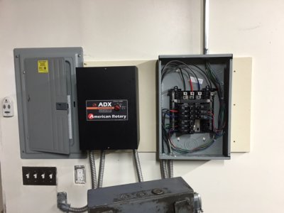
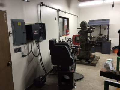
Here are a few pics of my recently completed three phase sub panel. I wired the panel using color coded wiring and pulled/pushed the individual wires through 1" conduit from the 3 Phase panel to individual junction boxes having 4 strand locking plugs. (I just know at some point I will replace or move these machines and put in something different-hence my decision to not hard wire the machines.)

The panel on the left is the 220/110 v shop master (sub panel) feed by the main at the house. The middle black box controls the 3 phase rotary power converter. It is feed from a separate breaker in the shop sub panel - exiting the wall from below the light switch in flexible armored conduit that runs into the bottom left of the box. The panel on the right is my three phase junction box, with one 30 amp breaker for each machine. (Total of three circuits with room for one more). Everything works! Each machine turns as it should. No explosions - which is a good thing.

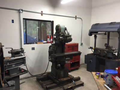
I have since moved the Van Norman mill off the transit pallet and put it on the floor. I may move the VN into the center of the bay opposite the lathe. In which case the conduit will,probably need to go up the wall and over across the top of the ceiling for 10-15' and drop down to the machine location. Still deciding about that... But here it is, mostly done.

image.jpeg image.jpeg
 
Out of curiosity- would it have been cheaper just to do single-to-three phase vfd's? I know 3 phase panels and breakers get expensive in a hurry.


Sent from my iPhone using Tapatalk
 
Back
Top