1 HP single phase wiring

autonoz

Active User
Registered
Joined
Oct 19, 2012
Messages
456
I am at the point of my referb where I need to test my motor. The picture is of the tag, re-written that was located in the wiring box of the motor. All I want to do is wire this to a power chord and plug it in to listen to the motor. I want to wire it at 120 which is the low voltage. I have never wired an electric motor to a power chord, but have done household wiring, so I am capable with some direction. Here is how I read the directions. For the 120 I need to wire nut the brown,green, and red wire together. Next I need to wire nut the white,yellow, and black wire together to one wire of the plug. Lastly I need to wire the Black/red wire to the other plug wire. Does this look correct? And what about a ground for a three prong plug? Am I close or way off?

And if I want to reverse direction it says interchange red wire with black wire. So do I put the yellow, white and red wire together on plug wire and wire nut the brown, green and black together?
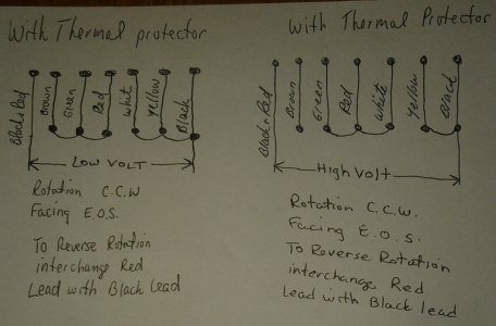
logan motor.jpg
 
Sounds like nobody wants to take the blame here... :D

But.. yeah, sounds like you're on the right track.
Not sure how you're going to be able to tell which one is neutral or L1. Or if it matters.

Generally the chassis is grounded to the green.
 
first let's identify your wiring for you.....

THESE ARE NEMA WIRE COLOR CODES FOR DUAL VOLTAGE SINGLE PHASE MOTORS
BLUE=T1
WHITE=T2
ORANGE=T3
YELLOW=T4
BLACK=T5
RED=T8

YOUR GREEN WIRE MAY BE A FADED BLUE COLOR, THE BROWN WIRE IS MOST LIKELY ORANGE FOR THE SAKE OF THIS APPLICATION

FOR CLOCKWISE ROTATION JOIN T1,T3,T5 AND CONNECT TO LINE 1(BLACK 115V IN)
THEN JOIN T2,T4,T8 AND CONNECT TO LINE 2 (WHITE 115V IN NEUTRAL).
FOR COUNTERCLOCKWISE ROTATION JOIN T1,T3,T8 AND CONNECT LINE 1(BLACK 115V IN), THEN JOIN T2,T4,T8 AND CONNECT TO LINE 2 (WHITE 115V IN NEUTRAL).
GREEN OR YELLOW/ WITH GREEN STRIPE ARE ALMOST ALWAYS THE GROUND LEG IN ALTERNATING CURRENT CIRCUITS.
DO NOT CONNECT GREEN TO LINE 1 OR LINE 2, THE GREEN GOES TO THE MOTOR FRAME GROUND
I HOPE THE INFO HELPS OUT!
LET ME KNOW IF THERE ARE OTHER QUESTIONS, I'M HAPPY TO HELP OUT.
MIKE:))
 
first let's identify your wiring for you.....

THESE ARE NEMA WIRE COLOR CODES FOR DUAL VOLTAGE SINGLE PHASE MOTORS
BLUE=T1
WHITE=T2
ORANGE=T3
YELLOW=T4
BLACK=T5
RED=T8

YOUR GREEN WIRE MAY BE A FADED BLUE COLOR, THE BROWN WIRE IS MOST LIKELY ORANGE FOR THE SAKE OF THIS APPLICATION

FOR CLOCKWISE ROTATION JOIN T1,T3,T5 AND CONNECT TO LINE 1(BLACK 115V IN)
THEN JOIN T2,T4,T8 AND CONNECT TO LINE 2 (WHITE 115V IN NEUTRAL).
FOR COUNTERCLOCKWISE ROTATION JOIN T1,T3,T8 AND CONNECT LINE 1(BLACK 115V IN), THEN JOIN T2,T4,T8 AND CONNECT TO LINE 2 (WHITE 115V IN NEUTRAL).

GREEN OR YELLOW/ WITH GREEN STRIPE ARE ALMOST ALWAYS THE GROUND LEG IN ALTERNATING CURRENT CIRCUITS.
DO NOT CONNECT GREEN TO LINE 1 OR LINE 2, THE GREEN GOES TO THE MOTOR FRAME GROUND
I HOPE THE INFO HELPS OUT!
LET ME KNOW IF THERE ARE OTHER QUESTIONS, I'M HAPPY TO HELP OUT.
MIKE:))

The wiring diagram in the OP is the diagram for my motor. I have six wires and they are the same as the diagram. I do not have a blue wire.
 
The motor must not have been made under the current nema coding, but no big deal....

Here's what we'll do, we will treat the green wire like it is the blue wire and make it t1
we will take your brown wire and make it t3
so to recap...

Green=t1
white=t2
brown=t3
yellow=t4
black=t5
red=t8
clockwise rotation join t1,t3,t5 put black from 115v supply on this connection, join t2,t4,t8 connect to neutral 115 (white)
ccw rotation join t1,t3,t8 put black 115v supply on this comnnection, join t2,t4,t5 connect to neutral 115v (white)

the only anomalies are the green and brown wires.
On either rotation, they are connected in the diagram ,so no harm will come to the motor as long as they are both connected to T5 OR T8.
IT APPEARS THAT THROUGH OSMOSIS THAT YOU MOTOR WAS RUNNING COUNTERCLOCKWISE BEFORE THE TEARDOWN, IS THAT CORRECT?

mike:))
 
The motor must not have been made under the current nema coding, but no big deal....

Here's what we'll do, we will treat the green wire like it is the blue wire and make it t1
we will take your brown wire and make it t3
so to recap...

Green=t1
white=t2
brown=t3
yellow=t4
black=t5
red=t8
clockwise rotation join t1,t3,t5 put black from 115v supply on this connection, join t2,t4,t8 connect to neutral 115 (white)
ccw rotation join t1,t3,t8 put black 115v supply on this comnnection, join t2,t4,t5 connect to neutral 115v (white)


the only anomalies are the green and brown wires.
On either rotation, they are connected in the diagram ,so no harm will come to the motor as long as they are both connected to T5 OR T8.
IT APPEARS THAT THROUGH OSMOSIS THAT YOU MOTOR WAS RUNNING COUNTERCLOCKWISE BEFORE THE TEARDOWN, IS THAT CORRECT?

mike:))

Not sure. I have never had the motor running or wired. Does the black with red stripes wire get connected to the other plug lead? Oh and by the way I said six wires, but it's seven. The black with red stripes.
 
7 wires makes a bit of difference then....
the diagram you had hand written would be correct for this motor. the confusing part was the number of leads.
 
I am at the point of my referb where I need to test my motor. The picture is of the tag, re-written that was located in the wiring box of the motor. All I want to do is wire this to a power chord and plug it in to listen to the motor. I want to wire it at 120 which is the low voltage. I have never wired an electric motor to a power chord, but have done household wiring, so I am capable with some direction. Here is how I read the directions. For the 120 I need to wire nut the brown,green, and red wire together. Next I need to wire nut the white,yellow, and black wire together to one wire of the plug. Lastly I need to wire the Black/red wire to the other plug wire. Does this look correct? And what about a ground for a three prong plug? Am I close or way off?

And if I want to reverse direction it says interchange red wire with black wire. So do I put the yellow, white and red wire together on plug wire and wire nut the brown, green and black together?

you will join 115v neutral(white) to black,yellow,motor white with a wire nut
then you'll join brown , green , red with a wire nut
then join 115v hot(black) wire to the red/black stripped wire with a wire nut

to reverse it's 115neutral, red, yellow,motor white ,wire nut
brown,green,motor black, wire nut
then, 115vhot(black) to red/black,wire nut

i would add an external ground to the motor frame, but the motor should run just as wired without external ground the motor is probably insulated very well.
i hope the info helps out.
mike:))
 
Having a ground wire is THE most important wire for motor wiring, in my opinion. "IF" something happens to a motor winding, you want somewhere for the electrical energy to easily go, so it can trip a breaker or fuse, making the machine safe. Motors usually mount on an adjustment plate of some sort, with bolts through painted, and maybe oily joints. Not a reliable (read SAFE) grounding path.

Ruben
 
Thank you for the responses. Sorry for the confusion. I will wire it this way to check the motor and come back with any questions I may have. I will be adding a switch once it is on the machine, so will need some direction. There is always a wealth of knowledge on this site. Thanks again.
 
Back
Top