2017 POTD Thread Archive

September 17
20170917_174145.jpg

October 19
20171019_185728.jpg

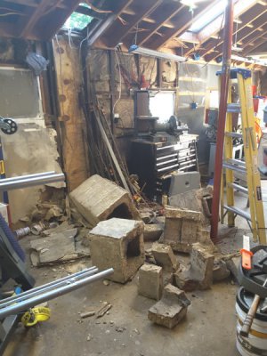
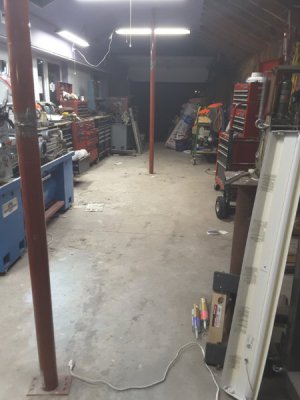
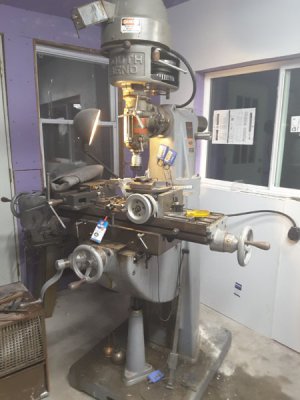
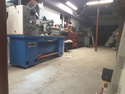
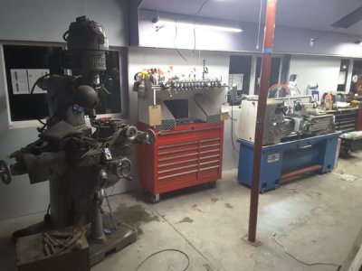
The red toolbox in the center of the two black boxes is where that chimney was... it's not done, but it sure is nice to see it to this point anyway. Stone arrives in about a week for the exterior, after the stone is up, siding on, soffit and facial all done... I'll finally get to the last wall in that section of garage...

20171019_185702.jpg
20171019_185814.jpg
20171019_185321_001.jpg

Rich
 
Made a specialised bike tool for a friend - boy that cycling thing seems expensive, the OEM tool seems to go for over $100 secondhand on Ebay.
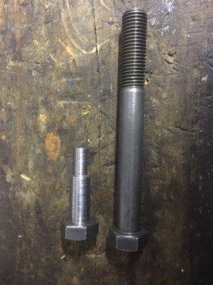
Started with a couple of bolts which were de-galvanised overnight in some vinegar then cut and turned to size.
IMG_4602.JPG

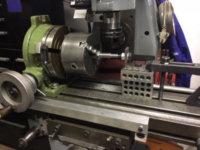
Then onto the mill to cut a 8 tooth spline
IMG_4661.JPG

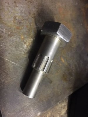
and the final tool.
IMG_4663.JPG
 
Made a specialised bike tool for a friend - boy that cycling thing seems expensive, the OEM tool seems to go for over $100 secondhand on Ebay.
Started with a couple of bolts which were de-galvanised overnight in some vinegar then cut and turned to size.
What is it used for?
 
Made a specialised bike tool for a friend - boy that cycling thing seems expensive, the OEM tool seems to go for over $100 secondhand on Ebay.
A new business venture for you? At $100 for a used one you should be able to make some decent money producing some of those. Maybe even look into other specialty bike parts.

Your friend must be very happy to have a friend like you.
 
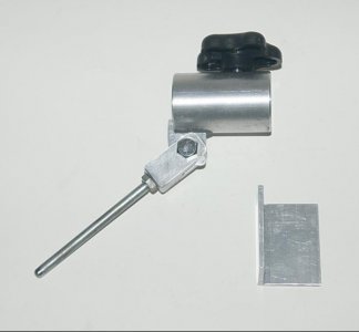
Today I completed a jig to hold a wood turning bowl gouge on the grinder to allow grinding a type of multi-sided grind called Fingernail Grind or Irish Grind or other names. This is for a fellow member of my local wood turning club.

This was made with mostly scraps.

The piece of angle is to be clamped/screwed to a bench at a set distance from the edge to allow consistent "stick-out" of the jig, which is important to enable getting the same grind each time.

Fingernail_grind_jig_with_stick-out-plate_8198.jpg

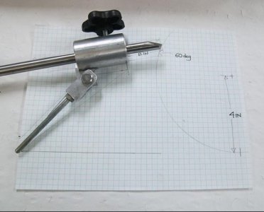
This gives an idea of how it is used. A sliding arm with a stop/hole at the end. This is positioned so the nose of the gouge will have the desired angle, for this gouge 60 deg.

The arm is designed to allow being set to different angles. The arm angle changes the grind angle of the "wings" on the side.

A 1/4in x 20 tpi bolt threaded into the pivot block, head machined round.

Fingernail_grind_jig_with_gouge_on_layout_8195.jpg

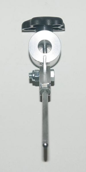
A view from the rear. A brass tipped screw engages inside the flute of the gouge to hold this in place.

C:\Users\pained\Pictures\Metalwork_Gallery\Projects\Ellsworth_jig\Les_Bailey\Fingernail_grind_jig_rear_view_8199.jpgFingernail_grind_jig_rear_view_8199.jpg

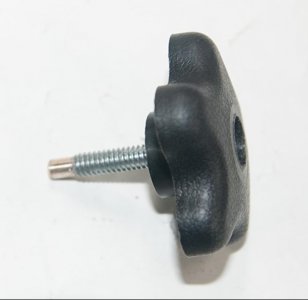
A plastic knob with embedded nut 1/4in x 20 tpi. Drilled out the top so the head of the bolt fits. Drilled out the end for a small brass tip epoxied in place.

Brass_tipped_screw_complete_mounted_in_knob_8188.jpg

There are a number of commercially available jigs, but I do love making projects like this.
 
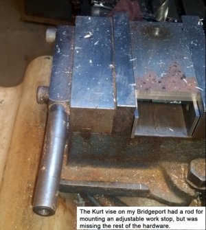
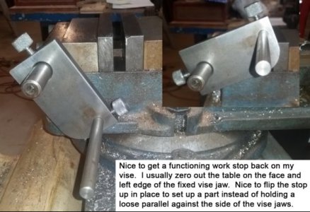
The Kurt vise on my Bridgeport had a ¾” diameter rod for a work stop, but that was it. So, POTD was making the rest of the stop.

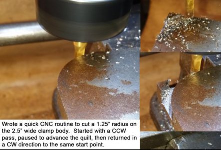
Used a piece of ½” thick CRS for the body. I wanted to be able to quickly drop the stop out of the way of the vise. Plan was to make a couple of knurled clamp screws for quick adjustments. The bar stock I grabbed was a little long and a little wide, so wrote a quick CNC routine to put a fat radius on one corner so it'd swing down out of the vise jaw opening.

I’m slowly getting more proficient with the CNC. Miss important details like ABS vs. INC table positioning and Rapid vs. Feed speeds. The controller naturally does whatever you tell it be it right or wrong. The piece was 2 ½” wide, so went with a 1.25” radius. The routine started at the top edge and worked to the LH side. Then paused for me to advance the quill, then returned to the starting point. Did the initial radius at 0.010” to the left and high to leave room for a light finishing pass. Did the cutting in Incremental mode, so it was easy to cut the radius a little short then creep up to the tangent points.

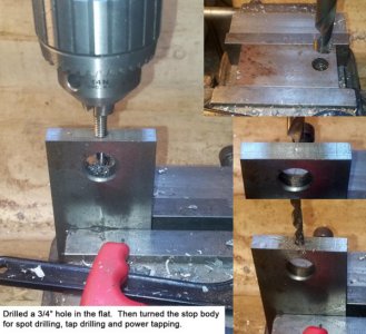
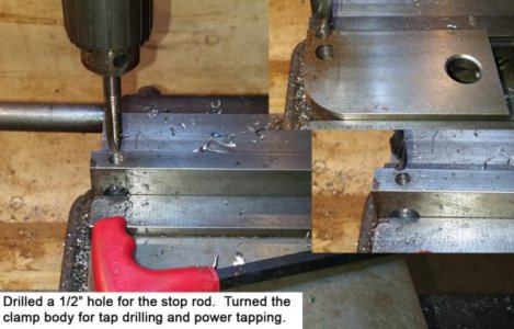
Drilled the through holes for the ¾” rod on the vise and a ½” hole for an adjustable stop. Drilled and tapped a couple of 5/16”-18 holes for lock screws. My first time power tapping which frankly is very nice. The machinists in our Tool Room at work call it “power snapping”; fortunately no issues for me.

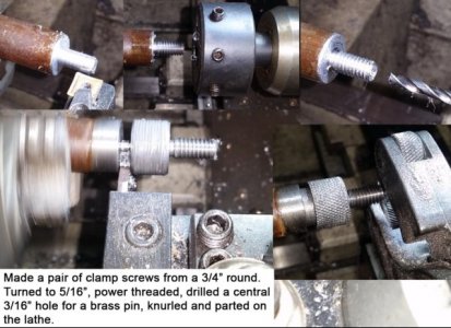
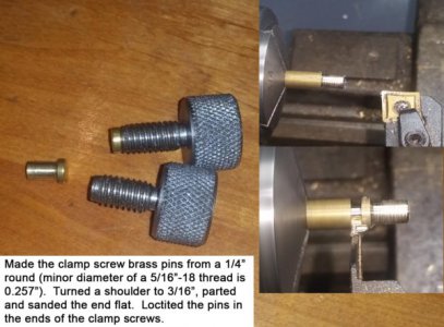
Turned a couple of clamp screws on the lathe from ¾” stock. Power threaded the 5/16”-18 thread here also. Drilled out the center of the screws for 3/16” diameter brass pins. Turned some ¼” brass down to 3/16” and parted to make a couple of soft screw ends on the clamp screws. The brass pins were Loctited into place.

Turned out pretty well. Thanks for looking.

Bruce

20171020_104152.jpg20171020_105840.jpg20171020_114605.jpg20171020_121535.jpg20171020_125857.jpg20171020_133621.jpg20171020_134130.jpg
 
What is it used for?
It is for disassimbling the rear free wheeling hub of a particular Shimano wheel assembly. Probably out of production as my friend is into older ‘classic’ bike parts. Not the first tool I have made for him and probably not the last.
 
Back
Top