New Ball Turner

JimDawson

Global Moderator
Staff member
H-M Lifetime Diamond Member
Joined
Feb 8, 2014
Messages
11,144
I have a project coming up that is going to require a ball turner. I could buy one, but what fun is that. ;)

The insperation for this design come from http://www.hobby-machinist.com/threads/just-finished-my-lathe-radius-and-ball-turner.61362/

I'm making it a bit different, but the same principal.

So head for the rack to find some material. Found a piece of 2x2 6061, and a piece of 1 15/16 rusty old hydraulic cylinder shaft. Not sure what it is, but has a light hard chrome surface and machines very nice. The chips come off like 41 something. And my Criterion 3 inch boring head. Ordered a few other bits & pieces from McMaster that aren't here yet.
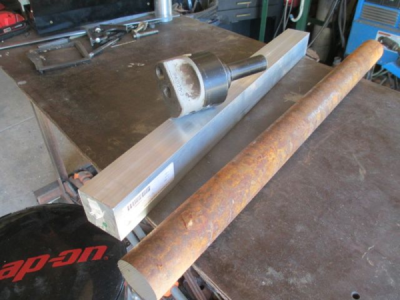
upload_2017-8-17_14-25-20.png

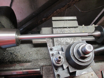
So first make the arbor. I left the bearing journals 0.010 over so I can fit later to the reamed hole in the aluminum mount. The new DRO on my lathe is great for laying out the steps on the arbor. Should have installed one a long time ago.
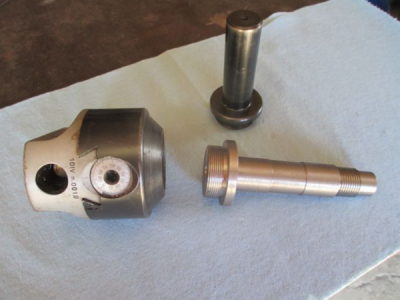
upload_2017-8-17_14-30-45.png

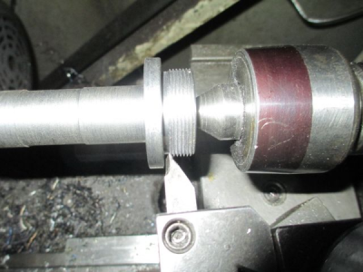
For those of you who have never done this before, here is my method of threading to a shoulder.
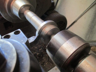
upload_2017-8-17_14-35-18.png

Turn the tool upside down and run the lathe backwards. That way you are feeding away from the shoulder.
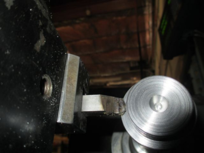
upload_2017-8-17_14-37-37.png

And another view
upload_2017-8-17_14-38-17.png

If will be a few days before I can update, waiting for my new dovetail cutter to cut the dovetail for the tool holder. I hope aluminum will work for a quick change, hope it's not too soft. I'll find out. If it doesn't work, I get some 4140 and make another.

Stay tuned for more......:)
 
Awesome! I saw the other post, got me inspired to make one also, I have an extra one of those 24 dollar 2" boring heads. I want to see how you go about yours.

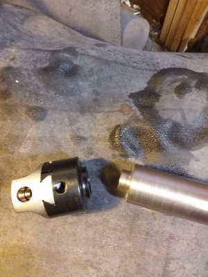
And I have to post a pic, I'm compelled, my threading worked and the boring head fits so nice lol I'm very proud lol20170816_195807.jpg
Crap, I uploaded one of the blurry pics, ok, just imagine the threads are all beautiful!...

Sorry, I'll be watching for now on, I promise... looking forward to how you do yours.

Rich
 
We interrupt this thread to bring you the following project.......

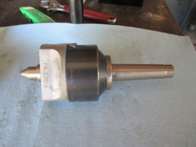
While waiting for parts for the radius turner, I decided that you can't a build new radius turner with out a cool handle to operate it. So time to build a tapered handle. But I don't have a taper attachment and the taper length is too long for the compound. OK, I could do it in 2 setups, but I have been meaning to build a boring head taper attachment anyway. So first I need to make a MT3 arbor for my boring head.

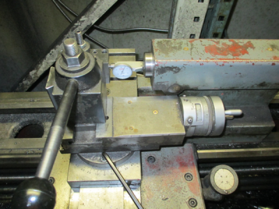
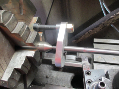
My tailstock is MT3, so aligning the compound to the taper. Run the indicator in and out with the compound, and adjust the angle until the indicator doesn't move over the length of travel.

upload_2017-8-19_18-26-38.png

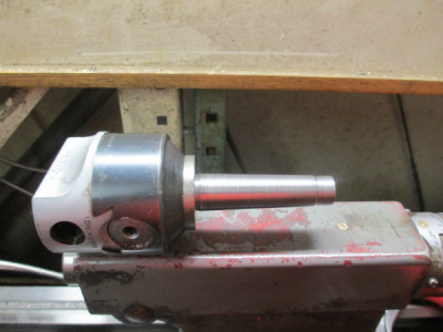
And presto, a MT3 arbor.
upload_2017-8-19_18-27-33.png

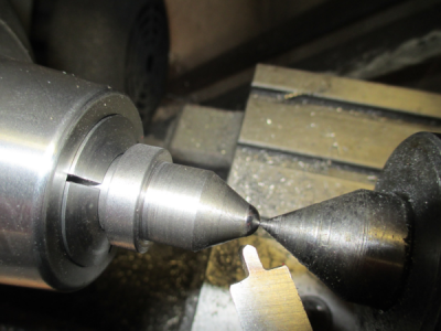
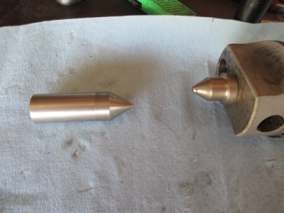
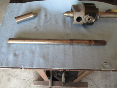
So now I need a center for the boring head. Because the part will be at an angle relative to the lathe centerline, a standard 60° center is not going to work. So I made a ball center out of a chunk of unknowdium tool steel that I had kicking around. Used a 0.312 bearing ball and using a 5/16 ball end mill created a pocket for the bearing. I went about 0.015 deeper than center, that way I had a little material past the center of the ball.

Holding the ball in place with the center.
upload_2017-8-19_18-33-35.png

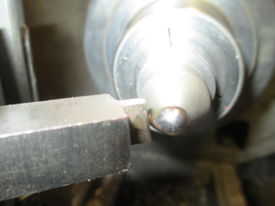
Then I swaged over the excess material with a radiused tool. This was done with the lathe turning at 70 RPM, I couldn't really see what was going on, I was just working by feel. Very much like metal spinning.

upload_2017-8-19_18-36-24.png

And here it is. The swaging worked as planned, the ball is captured, but can actually still rotate, much like a ball point pen.

upload_2017-8-19_18-40-41.png

Since I don't have a MT5 to MT3 adapter or a drive plate for my spindle, I whipped up a quick center that can go in the 4-jaw chuck.

upload_2017-8-19_18-42-46.png

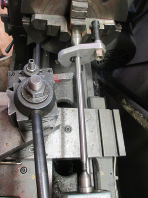
So next I need a lathe dog to be able to drive the shaft when mounted between centers. Grabbed some 1/2 aluminum tooling plate off the shelf and instant lathe dog. There are no good pictures that show the shape of the shaft hole, but it is a teardrop shape.

upload_2017-8-19_18-48-10.png

I found this piece of 3/4 inch shaft on the shelf, not sure what material, but it's tough enough to have a spline on the end. I think it was out of a rototiller or something like that. But I think there is a radius turner handle hiding in there somewhere. ;)

upload_2017-8-19_18-55-17.png

First I turned the shaft down to 0.500 and threaded the ends. It will taper from 0.500 at one end to 0.375 at the other.

upload_2017-8-19_18-58-35.png

And here is the setup. A few layers of emory cloth to protect the shaft from the set screw in the lathe dog.

upload_2017-8-19_18-51-5.png

And another view

upload_2017-8-19_18-59-42.png

Worked as planned and I now have a handle for the radius turner. :)

We now return you to the regularly scheduled thread :grin:
.
.
 
Last edited:
Tuned into channel , reruns are done waiting new response to video library. Nice job so far. Like the ball center , should work great on tapers. Both ends yupp
 
A little update. I want to cut a slit for bearing adjustment like @Technical Ted did with his radius turner http://www.hobby-machinist.com/threads/just-finished-my-lathe-radius-and-ball-turner.61362/

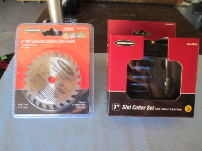
But I didn't have a slitting saw and I want a better job than the band saw would do. So while I'm waiting for parts, I'll make a slitting saw for the mill. So off to Harbor Freight to pick up a set of slot cutters. On a whim I grabbed the 4 inch saw blade also.

upload_2017-8-21_0-6-11.png

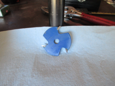
On closer inspection I decided that I didn't like the slot cutters, too much unsupported carbide sticking out. So I'll use those for something softer than aluminum.

upload_2017-8-21_0-35-32.png

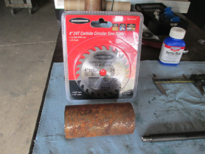
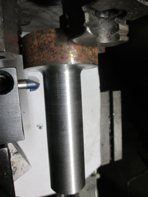
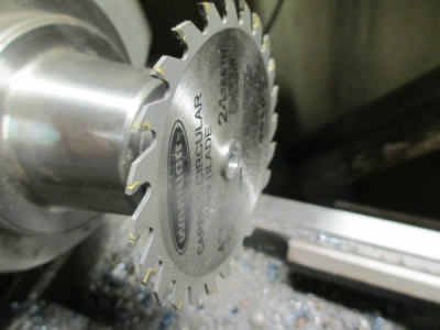
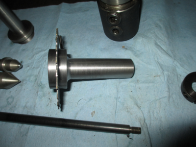
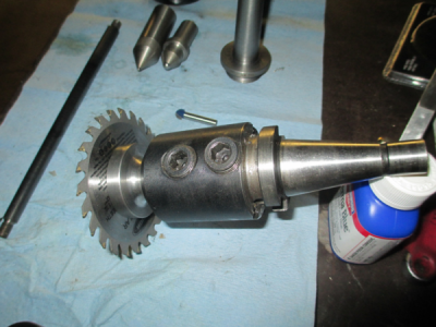
So that leaves the saw blade. That and a chunk of that rusty old cylinder rod will make a perfect slitting saw.
upload_2017-8-21_0-10-3.png

Turned the shaft down to 1 inch to fit my big end mill holder. Left it 0.005 oversize and some extra in the corner for the radius. Then finished it off with a 3/8 carbide radius cutting router bit.
upload_2017-8-21_0-14-0.png

Then into the collet chuck to finish the other end.
upload_2017-8-21_0-16-29.png

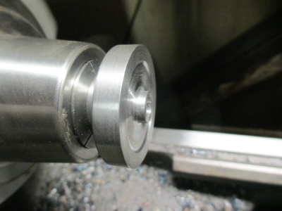
There is a pocket in the end cap that the nose sticks into to keep things centered up.
upload_2017-8-21_0-18-45.png

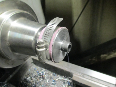
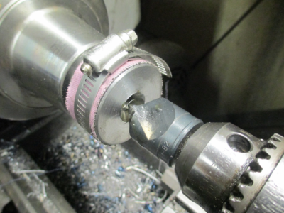
The end cap is pretty much a mirror image of the arbor. I secured it with a screw to face off the back side and turn the OD. But now I have to countersink for a flathead cap screw. If I take the cap screw out, the cap will fall off. So how to hold things together while countersinking? Simple........

A hose clamp and some emory cloth. All it has to do is drive the cap while countersinking. The cap is centered by the nose on the arbor. All of the working pressure is towards the spindle.

upload_2017-8-21_0-25-9.png


Worked perfectly.
upload_2017-8-21_0-26-19.png

And here it is
upload_2017-8-21_0-27-5.png

And another view

upload_2017-8-21_0-27-48.png

We'll see how this works out. You can't beat $5 for a carbide tooth slitting saw. And 0.070 kerf will be perfect for the slot I want to cut.
 
I have quite a bit done now. While I was waiting for a dovetail cutter I decided that the ball turner should have some stops......So..... (I'll show this assembled later, then it will make sense)

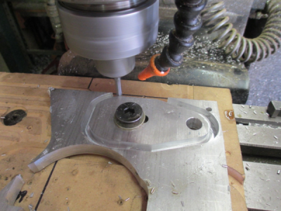
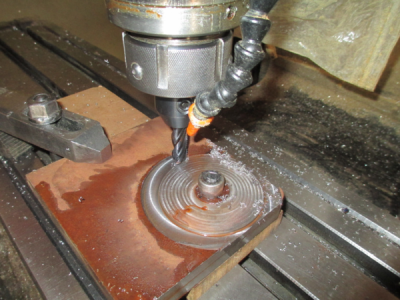
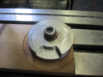
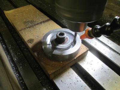
A chunk of 3/4 inch A36 off the shelf. It is secured with a T-nut and a clamp over a piece of MDF as a spoil board. First operation was to face off the top, then rough out the OD with a 1/2 inch rougher. A really fast shutter ''stops'' the spindle, it really turning at about 600RPM. 0.060 DOC at about 5 IPM

upload_2017-8-26_23-7-42.png

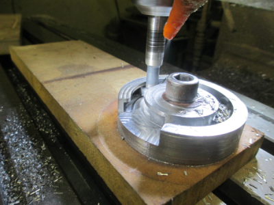
Next operation was to pocket out the T-nut entry area.
upload_2017-8-26_23-8-46.png

Then create a slot for the T-nut cutter. Using a 1/4 inch, solid carbide router bit. Made a slot 0.325 wide to fit the 0.320 shank on the T-slot cutter. I was going to make this whole assembly a bit smaller, but I had to fit the project to the tools I had and this is the minimum size I could make the piece and have everything fit.

upload_2017-8-26_23-13-53.png

This is where the pucker factor went up quite a bit. :eek: This had to be done in one cut, and the tool bit had been modified for another project so there wasn't much shank to grab onto. All went well :)
upload_2017-8-26_23-17-20.png


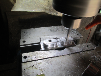
T-slots need T-nuts. So making a couple of radius T-nuts out of some 1018 CR I had kicking around. First carve them out of 1018 leaving 1/8 or so material on the bottom to grab with the vice jaws. Using the same 1/4 inch router bit as in the slotting operation above.

upload_2017-8-26_23-25-49.png

Then flip them over in the vice and machine away the excess material. I had to change vice jaws for this operation because I couldn't hang on to them with the step jaws. There is almost 0.010 clearance between the cutter and the hard vice jaws :eek:. I rarely use hard jaws, but I didn't feel like making another set of soft jaws right then.
upload_2017-8-26_23-29-7.png

And they fit the slot perfectly. I made them to have 0.005 clearance all around.
upload_2017-8-26_23-31-4.png

I also have the main body nearly complete, I'll post that update tomorrow. Just have to cut the slot. That should be interesting, we'll see how the HF saw blade works out.:rolleyes:
 
Jim, please help me out here. As usual, I am in awe of the incredable work you do, but I need some answers so that I don't feel like a complete failure as a BEGINNER hobby machinist. First off, I hope you are going to tell me that your mill is CNC, otherwise I have no clue how you are making all those round and curved features. Also when you say "Using a 1/4 inch, solid carbide router bit" are you talking about a normal bit used for woodworking? I've seen you using them in aluminum before, but this is steel right? I assume the T-slot cutter is an actual milling cutter, but I could be wrong there also. I loved the use of the HF carbide saw blade as a slotting saw,and look forward to seeing it in use. Thanks to you whenever I turn questionable (possibly hard) steel I have a good assortment of HF brazed carbide tool bits that I sharpened using a 10 dollar HF diamond wheel. I know, I know, you insist that they can be sharpened on a regular AO wheel. Sorry for all the gushing, but I just love reading about the projects you, and the other great machinists on this forum make. Anyway, looking forward to your answers, Thanks, JR49
 
First off, I hope you are going to tell me that your mill is CNC, otherwise I have no clue how you are making all those round and curved features.

Yes, my mill is both a CNC and manual. Having a CNC has allowed me to expand the range of parts I can make and even makes me look like a machinist. ;) About 4 years ago I couldn't even spell CNC. It would be possible to make all of the parts shown on a manual machine, but it would take forever. A lot of setup time on a rotary table.

Also when you say "Using a 1/4 inch, solid carbide router bit" are you talking about a normal bit used for woodworking? I've seen you using them in aluminum before, but this is steel right?

Yup, Diablo upcut spiral from Home Depot. Lowes sells an equivalent in the Bosch brand. And the best part is that you can get one on a Saturday afternoon. They work in all materials, even stainless steel. With a 1 inch cut length they are a bit spindly so you have to be careful. I wish they had a 3/8 solid carbide. I also use carbide tipped router bits in all materials.

I assume the T-slot cutter is an actual milling cutter, but I could be wrong there also.

Yes, it is a standard T-slot cutter designed for metal work. I bought that one for a special project and had to grind the shank down to get clearance. I normally would not have that much tool hanging out.

Sorry for all the gushing, but I just love reading about the projects you, and the other great machinists on this forum make. Anyway, looking forward to your answers, Thanks, JR49

Thank you for the kind words. :) There are a lot of very talented people on this forum, and like you, I enjoy seeing the beautiful projects done by the members.
 
Back
Top