-
Welcome back Guest! Did you know you can mentor other members here at H-M? If not, please check out our Relaunch of Hobby Machinist Mentoring Program!
You are using an out of date browser. It may not display this or other websites correctly.
You should upgrade or use an alternative browser.
You should upgrade or use an alternative browser.
[How do I?] Modifying a snow plow
- Thread starter dave_r_1
- Start date
I got a chance to use it on a couple of driveways today, and it worked pretty well. We got about 2" of wet snow Thursday afternoon/evening, and I went out today, and it had mostly melted (anywhere that got direct sunlight for several hours), but shaded places still had most of it, with a layer of ice at the bottom, then snow partially frozen together on top (because it was about freezing overnight, the water in the snow makes it crusty).
I doubled the weight on the front (went from 70lbs to 140 lbs of weight), and this helps the front end stay down while pushing (the plow itself "floats" on the surface, and the drive wheels want to make it do a wheely, as they are really quite powerful, especially with nothing else (like, say a bunch of spinning blades cutting the heads of millions of defenseless blades of grass) to soak up power from the 22hp engine.
It can't clear anything packed down by a vehicle (there's no significant weight on the blade and overall the unit is maybe 600 lbs or so), but it had no problem pushing a 6" tall furrow (windrow of snow piled up by a couple of passes with a power brush) 40' long or so, no problem with traction even with that layer of ice that was on the concrete.
Unfortunately, I think I will basically have to redo pretty much everything to make it work better.
It would work better:
-with a slightly longer wheelbase, as going up the ramp, the center of mass is really close to the drive wheels and I had to make sure the front wheels stayed down. But if I happen to slip...that's a train wreck I really don't want to happen.
-the point of attachment for the plow is bad, too close to the ground (2.5" up, maybe 3 or 4 inches behind the drive wheels, so it hits the ground before the drive wheels get traction on the ramp. Putting a length of 2x6's in front of each ramp avoids the problem, but it would be better overall if the mounting point was in front of the drive wheels and higher up. I'll look at some atv front mounts for modifying them to fit, as well as consider shortening the current setup and bending/angling the tubes so the mount can be a couple inches higher
-the winch control would be more convenient if it could be used without having to lock the controls (the drive unit is such that you HAVE to lock the controls in neutral before removing your hand, otherwise it shoots forward at full speed until the deadman switch kills the motor)
-the winch needs to be raise a couple of inches so the plow trip spring doesn't rub on it (I should have noticed this when I made it, but I didn't think about the fact that the spool is what is centered, not the overall winch).
-needs larger, wider front wheels, as the current ones (about 5" diameter) have some trouble in softer snow as well as not handling even the 2" lip on the ramps.
So, I'll have to get started on V2...
- Joined
- Feb 16, 2014
- Messages
- 60
The first thing I thought of, when I read you wanted to make it narrower, but be able to restore the full width.........V plow.........You could hinge the blade in the middle, and let each end sweep back to make it narrower, or swing the ends out to make it back into a dozer blade. This could also allow you to set it the width of any unusual width sidewalks you want to clear, without extending out over the grass, depending on how much swing you could get out of each side of the blade.
A v-plow would make it narrower, but also would make the unit longer, as it needs to be more out front for the plow blade to be able to retract without hitting the front wheels. As well, this plow has the angling mechanism front and center, right up against the plow in the middle, and is the main point where the plow connects to the mount. It would be totally overkill for how I would use it.
And I am really bad at hinges. :-(
And I am really bad at hinges. :-(
Finally started cutting into the plow.
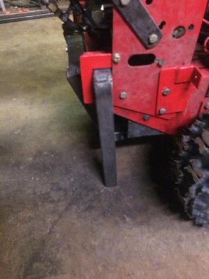
First, needed to make a kickstand for the base unit, as it likes tipping over backwards (just square tubing at a 90º angle, slides into the mount I made to hold the engine for a powered bagger unit when I'm using it for mowing):
Here are pictures of the result for one side, held together with 9/16" solid steel rods.
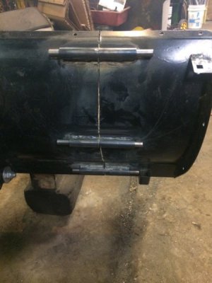
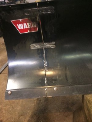
I started cutting 6" lengths of thick wall 9/16" pipe, then drilled out the pipe with a 9/16" drill bit so the 9/16" steel rod would slide easily within it. Then I ground off the paint where I was going to weld the alignment pipe, lined up the pipe so it was parallel to the blade, then welded them in place. After this, I marked the cut line on the blade side, and used a cutoff wheel on an angle grinder to cut the end off, also having to flip it over to cut through the alignment pipes and some support braces on the back side.
This kind of worked, as I can get it together and it certainly feels very solid, but I need to use a BFH to get the pins in and everything together. Likely, the heat from welding the alignment pipes put some stress in the metal, and the curvature of the blade between the two sides is slightly off. Tomorrow, I'll try "adjusting" the curvature to try to eliminate/at least reduce the need for a BFH to get that side on.
When I do the other side, I'll try putting a "rib" out of 1/8" flat steel on each side of the cut line (on the back, like Warn did on the end of the plow) to minimize the warping of the blade (actually, I'm kinda torn about doing this, as it would make "adjusting" the blade more difficult if it does still warp). I'll also add these ribs to this side, just to strengthen the new end of the blade.
I also need to drill hole for another plow bolt to hold the scraper blade on the end piece in place.
First, needed to make a kickstand for the base unit, as it likes tipping over backwards (just square tubing at a 90º angle, slides into the mount I made to hold the engine for a powered bagger unit when I'm using it for mowing):

Here are pictures of the result for one side, held together with 9/16" solid steel rods.


I started cutting 6" lengths of thick wall 9/16" pipe, then drilled out the pipe with a 9/16" drill bit so the 9/16" steel rod would slide easily within it. Then I ground off the paint where I was going to weld the alignment pipe, lined up the pipe so it was parallel to the blade, then welded them in place. After this, I marked the cut line on the blade side, and used a cutoff wheel on an angle grinder to cut the end off, also having to flip it over to cut through the alignment pipes and some support braces on the back side.
This kind of worked, as I can get it together and it certainly feels very solid, but I need to use a BFH to get the pins in and everything together. Likely, the heat from welding the alignment pipes put some stress in the metal, and the curvature of the blade between the two sides is slightly off. Tomorrow, I'll try "adjusting" the curvature to try to eliminate/at least reduce the need for a BFH to get that side on.
When I do the other side, I'll try putting a "rib" out of 1/8" flat steel on each side of the cut line (on the back, like Warn did on the end of the plow) to minimize the warping of the blade (actually, I'm kinda torn about doing this, as it would make "adjusting" the blade more difficult if it does still warp). I'll also add these ribs to this side, just to strengthen the new end of the blade.
I also need to drill hole for another plow bolt to hold the scraper blade on the end piece in place.
- Joined
- Jan 2, 2014
- Messages
- 8,852
Maybe drill them out to 5/8", use 5/8" pins to align everything while welding, then later use the 9/16" pins for regular use.
Basically it gives you some wiggle room for the welding warp.
Of course you may need a hammer and punch to remove the pins used for alignment during welds.
-brino
Basically it gives you some wiggle room for the welding warp.
Of course you may need a hammer and punch to remove the pins used for alignment during welds.
-brino
I looked at what I had done yesterday, and it turned out not as bad as I thought. After pounding out the pins and doing a bit more testing, and a little application of a BFP (person, me), the bottom two pins are perfectly aligned, and only the top one is a little bit out.
I went ahead and did the other side like the first, and it also turned out the same, the bottom two pins were nicely aligned, and the top one is just a smidgen out.
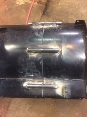
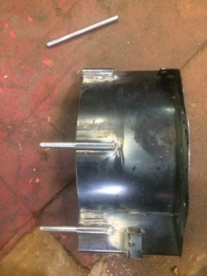
I welded the two bottom pins in, and it slides in and out pretty easily. The top pin slides in afterwards partially, so I'll try welding some ribs in to align them that last little bit.
I bought a jigsaw to make the ribs, and a flap wheel for my angle grinder (which worked MUCH better at just removing the paint from where I welded the pins to the blade).
I'll take it out on the park tomorrow and see how it works on the little bit of remaining snow that's there, but it feels pretty solid and doesn't wiggle a lot.
And I might drill out the receiving pipe sections just a little bit more (maybe to 19/64 from 9/16) to allow for rust/paint, as right now, they are a pretty tight fit.
I went ahead and did the other side like the first, and it also turned out the same, the bottom two pins were nicely aligned, and the top one is just a smidgen out.


I welded the two bottom pins in, and it slides in and out pretty easily. The top pin slides in afterwards partially, so I'll try welding some ribs in to align them that last little bit.
I bought a jigsaw to make the ribs, and a flap wheel for my angle grinder (which worked MUCH better at just removing the paint from where I welded the pins to the blade).
I'll take it out on the park tomorrow and see how it works on the little bit of remaining snow that's there, but it feels pretty solid and doesn't wiggle a lot.
And I might drill out the receiving pipe sections just a little bit more (maybe to 19/64 from 9/16) to allow for rust/paint, as right now, they are a pretty tight fit.
Went and got some grade 5 carriage bolts for holding the scraper blade securely to the two removable end pieces of the blade, then went for a spin on a local park. It did a reasonable job of pushing the snow to one side, with wet snow that had partially melted/frozen, so it was also crusty
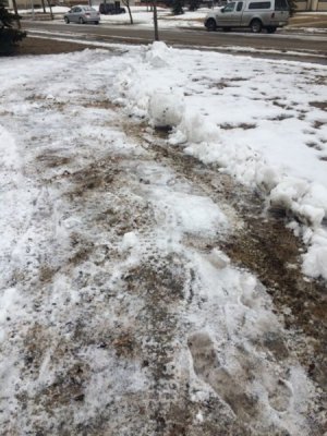
However, I went to another part of the park, where there is a buried sidewalk that never was cleared during the winter, and it had more trouble with clearing that, but there was more ice on it, and one of the two drive tires was really low (I have to see if it got punctured or just mounted poorly on the rim, both tire and rim are brand new). As well, once I returned to my garage, I noticed that one end piece had been bent backwards a little over 1/4".
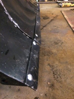
This is the end piece, which didn't appear to bend at all (either the pin or any part of the blade).
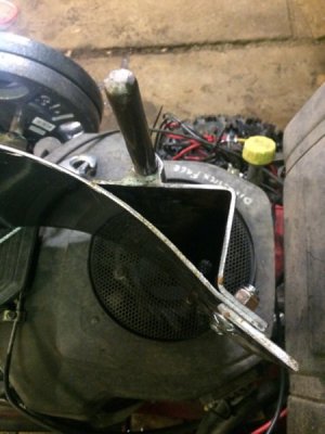
The main center part,with the angled brace running along the back lower edge of the blade, the part where I welded the pipe to it was flat and only welded to the blade intermittently, so it could relatively easily bend away from the blade.
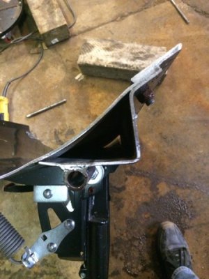
I managed to persuade it almost all the way back in place, and so I could slide the end piece on and off again, but I also will weld the brace to the blade near where I cut it off, as well as weld in a triangular insert to fill that area, so that if it bends at all, the whole end of the blade will have to bend.

However, I went to another part of the park, where there is a buried sidewalk that never was cleared during the winter, and it had more trouble with clearing that, but there was more ice on it, and one of the two drive tires was really low (I have to see if it got punctured or just mounted poorly on the rim, both tire and rim are brand new). As well, once I returned to my garage, I noticed that one end piece had been bent backwards a little over 1/4".

This is the end piece, which didn't appear to bend at all (either the pin or any part of the blade).

The main center part,with the angled brace running along the back lower edge of the blade, the part where I welded the pipe to it was flat and only welded to the blade intermittently, so it could relatively easily bend away from the blade.

I managed to persuade it almost all the way back in place, and so I could slide the end piece on and off again, but I also will weld the brace to the blade near where I cut it off, as well as weld in a triangular insert to fill that area, so that if it bends at all, the whole end of the blade will have to bend.


