Having trouble after QCTP install.

What did you have for your old tool post? The second photo shows what appears to be a negative rake on the top surface. This will work with a lantern type tool post as they angle the cutting tool up so you would end up with a zero or negative rake. Aloris type QCTP presents the tool horizontally so typically, the top of the cutting tool will be parallel to the shank or ground to provide a positive rake. A negative rake is essentially a drag type cut or scraping. Increased forces associated with negative rake tooling will expose issues with machine and/or workpiece rigidity which will cause chatter.
I did have a lantern tool post. The picture is a bit deceiving, there is a worn area on the tip and it needs to be reground, but it wasnt cut with a negative rake intentionally. I tried several different tools all with the same effect, some home ground and some store bought, no real difference there. I will try to correct the issue with the front saddle gib when I get home and then will work on making sure the chuck is centered correctly. I am sure there are more things that will pop up, and correct me if I am wrong, but those are fairly major things that need to be corrected ASAP.

Thanks again!

Jason
 
Part bubble numbers 199 and 307 (or 397) are carriage hold downs (and there is no carriage gib on a V-bed carriage). This shouldn't have anything to do with your chatter ...
Actually Logan calls them a Saddle Gib in the parts breakdown that the OP is looking at. Also, if he can lift either side of the saddle as much as he is indicating, that will more than compound other issues resulting in chatter.

I'm not saying that this is his only issue either ... that tool doesn't look like it has much rake.
 
Yeah, I remembered that Logan had made that mistake after I had posted. The other thing that surprised me was that there were no adjusting shims shown.
 
Jason,

I didn't see it earlier as for some reason my browser went to Ed's post. The normal (I would say proper but someone would probably take exception) orientation for a QCTP that has provision for attaching holders in two positions is that the CW one should be parallel to the lathe longitudinal axis and the CCW one perpendicular and on the left side of the post. This means that if you rotate your compound swivel for some special purpose, you need to realign the TP. The quick way to set it is to tighten the hold down bolt or nut finger tight. Mount your system test bar (everyone should have one) between centers and with the wedge or piston retracted advance the cross slide to bring the TP front face up against the bar. Fully tighten the bolt or nut. If on your TP, the front face isn't flat, mount a #1 or #2 holder (AKA #101, 102, 201, 202, etc.) on the front and run that up against the bar.
 
I don't have a test bar. I used the face of the chuck to square the tool post.

Jason


Sent from my iPhone using Tapatalk
 
To eliminate as many variables as you can I would suggest mounting your 4 jaw chuck and using your indicator to dial in your piece to get it running true, then make your test cuts and report back. If you are still getting a poor surface finish at least you have eliminated the chuck as a problem. I would also work on the rear saddle gib to snug it down to where it removes as much vertical play as you can without getting the carriage hard to move == Jack
 
A few observations.

The bad cut looks like screw threads so if not threading then you are trying to cut too fast...feed SLOWER.

Next change your setup and swing the compound away from the Chuck so it is to the right as you look at it.

Change the stick out of your cutter to MINIMUM as that small cutter is sticking out way too far so it can "lever" or give a bit as it bites.

Have the tool at 90 degrees to the work and at center line with everything close as these small lathes combined with possible gaps in the ways everywhere allow all of these gaps to compound.

The long stick out of the cutter gives it leverage to increase force o. Tool post that now is not on center of Carriage which allows it to lever against the ways differently.

I would guess a dial indicator in the correct spot would show movement of parts that should not move as the tool bites material.

Sent from my SAMSUNG-SGH-I337Z using Tapatalk
 
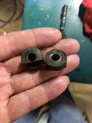
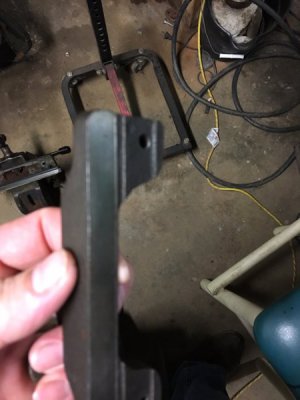
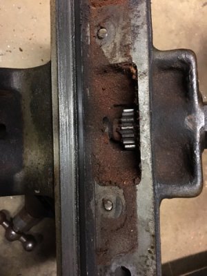
OK, I made it back home and took the saddle off. The gib has not been touching at all. The spacers gib spacers (item 348) are round with a relief cut in ONE end. It looks as though if your going to use something round as a spacer it would have a relief (flat) cut on both ends so it could hold the gib parallel with the saddle and the ways. Have I the wrong parts, or am I missing something. I will send pics of what I have.

Jason
 
pics of gib, spacer and underside of sadddle. dirty stuff there!
IMG_1226.JPG IMG_1227.JPG IMG_1228.JPG
 
Last edited by a moderator:
FYI that is sawdust from the wood working shop this lathe lived in. oil and dust mix very very wel..
 
Back
Top