So How Did I Do & What Do I Need ??...

OK, Got the back gear adjusted to where it stays engaged while running. Turns out it was just the set screw that adjusts the back gear was a bit too loose. Tightened it down just a bit and it works fine now. Today I took some of the lead screw gearing apart to give it a good scrubbing and I have a few questions before I try to take the gearing any further apart...

Should the large gear that attaches directly to the lead screw come off the shaft freely so that the entire gearing bracket can be removed ?? It seemed to be stuck so I didn't want to try to force it. Also I noticed the threading dial wasn't working correctly when engaged to the lead screw. It's very strange since it seems to work correctly when moving the carriage assembly manually ??? I can turn the handle and the threading dial turns with the carriage movement but when I engage the half-nut lever the carriage begins to move but the threading dial does not .....??????? I'm kinda stumped on that one and the manual doesn't offer any suggestions.
 
56type,

Short answer is "yes", the large gear on the lead screw should come off freely. It is commonly called the "screw gear". If you look at the threading chart, you will see that various threads require various screw gears. And although all of the listed feeds use the same 64T gear, two are with it mounted after the spacer (F) and two before the spacer (B).

Your threading dial is behaving normally. Read the sticky message on this subject located in the little area at the top of the first page of this Forum.
 
To save yourself some money learn how to use that four jaw chuck properly means you don't really need a three jaw chuck .
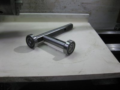
A very useful home made tool for ensuring you get the work piece centered as accurately as possible is to have a round bar that you have fitted a decent quality small sealed bearing on the end .
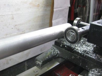
You put the bar in the tool post and advance the bearing till it touches the work piece , turn it 180 degrees by hand and see if it touches the other side .. adjust a couple of times till it does . now at 90 degrees to the first face you used & repeat the operations again.

The idea is to get it so that the bearing just drags on the work piece surface at every 90 degrees , this centre will be amazingly accurate.

Which brings me to centre point drills . Buy a new set of three different sizes , as you'll rarely ever find a second hand set is any good . Whenever you can , only center point drill the true centre from a rechecked & confirmed lightly dot punched mark you make in a turned face .

Getting a set of a tapered centers , A dead one that fits the head stock and a live centre that fits the tail stock .
Then make yourself a set of driving dogs and a face plate the face plater being as big as you can get to run on your lathe . My first dogs were my own home made ones made turned up ones from 1" thick engineering plastic like big flat washers . in 1, 2 & 3 & 4 inch dia capacities .

Once all done ( good turning practice and leaning how to cut a thread , turn the face plate true when it's mounted in the headstock .
You will now be able to turn bars very very accurately and also put a part turned item back in between the centers with maximum accuracy every time . You'll also find that if you make a set of clamps with coach bolts to fit them in the face plate from square bar or flat plates you can mount things larger than your chuck well off centre and turn them up so long as the article can rotate 360 degrees without fouling the bed of the lathe.


Another cheap tool I've found invaluable both on lathe & general metal work is a set of internal & external hand calipers with a simple resistant plastic washer in the pivot joint . I made my first set out of aluminium sheet scrap as that's all the metal I had , then replaced them four years later with purchased second hand garage sale carbon steel ones .
With these calipers you can accurately repeat a diameter you have measured/ checked to within two thousand of an inch or less once you learn how to " Get the feel " of them .
You can also set them accurately to about 1/100 of an inch , adjusting them by directly reading the scale off a quality engineers steel scale / steel ruler .
 
Last edited:
56type,

Short answer is "yes", the large gear on the lead screw should come off freely. It is commonly called the "screw gear". If you look at the threading chart, you will see that various threads require various screw gears. And although all of the listed feeds use the same 64T gear, two are with it mounted after the spacer (F) and two before the spacer (B).

Your threading dial is behaving normally. Read the sticky message on this subject located in the little area at the top of the first page of this Forum.

Thanks for the help. The compound gear bushings (M6-70) and change gear sleeves (M6-73) were stuck to the carriage bolts as well as the 64-T gear & spacer (M6-165) being stuck to the lead screw shaft. After some cleaning and persuasion with a plastic faced jeweler's hammer I got them to release and after a thorough scrubbing in some denatured alcohol everything went back together smoothly. Appreciate clearing up the mystery of the threading dial, I now understand that it is to be used to indicate where/when to engage the half-nut to get repeatable threading for each pass.
 
To save yourself some money learn how to use that four jaw chuck properly means you don't really need a three jaw chuck .
A very useful home made tool for ensuring you get the work piece centered as accurately as possible is to have a round bar that you have fitted a decent quality small sealed bearing on the end .
You put the bar in the tool post and advance the bearing till it touches the work piece , turn it 180 degrees by hand and see if it touches the other side .. adjust a couple of times till it does . now at 90 degrees to the first face you used & repeat the operations again.

The idea is to get it so that the bearing just drags on the work piece surface at every 90 degrees , this centre will be amazingly accurate .

Thanks. Would you happen to have a pic of the above mentioned centering tool, or post a link to it so I can get a better idea of it's construction and see the procedure in action ?? Trying to picture how this works.....

Currently looking at this tooling package from Littlemachineshop.com ....since my machine was missing the tool post when I bought it.

http://littlemachineshop.com/products/product_view.php?ProductID=3593&category=
 
That looks like a pretty good tooling package for the 6" MK2. You should also buy 2 or 3 extra #001 and/or #002 cutter holders (the more the better). Else, with only one holder of each type, if you need to change cutters or boring bars during the course of a job you will have to spend several minutes with an Allen wrench changing the cutter. And then a few more minutes getting the different type cutter on center. Which is no better than the lantern type tool post. With several quick-change holder with cutters already mounted in them, it only takes a few seconds to change tooling. At last count I had 11 of them, with all but two with cutters or bars mounted and centered.

Also, where the Little Machine Shop ad talk about cutting of a "tank", he means a "tang". The tang sticks out of the small end of the 1MT arbor and is used in drill presses with a tapered bar and slot cut through the DP quill to remove the (probably) drill chuck from the spindle. In your tailstock, you remove an arbor from the tailstock ram by retracting the ram until the end of the feed screw contacts the small end of the arbor, pushing it out of the taper. The tang adds additional length to the arbor and will cause the chuck to eject with an appreciable amount of the ram still exposed. It reduces the depth of hole that you can drill without repositioning the tailstock. After you cut the tang off, close the chuck jaws and mount the chuck in the spindle chuck with arbor sticking out toward tailstock. Face the cut off end smooth. Else you could bend your tailstock feed screw.
 
I very much agree with Robert, while you are paying shipping order more tool holders. If you look at the package of insert lathe tools and want to use them all, you will need holders or else be fooling with set screws. I also have about a dozen for my Atlas 6". I have one dedicated to a tool post grinder as well as a dial indicator for adjusting the 4 jaw. Saves setting up the magnetic base indicator holder.

David
 
Thanks for the tooling suggestions. I'm making a list as they come up so I can make "one haul do it all" when it comes to the shipping costs. Does anyone have a source for the nut that secures the compound slide handle ?? Just noticed mine is missing and would like to replace it without having to buy the complete screw assembly off ebay. Thanks.
 
56,

I don't know of a ready source except probably Clausing. And although they probably aren't expensive, the shipping would be. You can make one fairly easily. All that you need is a short length of all-thread and three hex nuts of the proper thread. Run the three nuts onto the all-thread until the outer one lacks about one thread of being flush with the end. With two open end wrenches, tighten the three nuts together. Turn the outside of the nut on the end down to the proper diameter. Do NOT try to make two at the same time as you will have no way to loosen them for removal. You may need to face off the outer end - I don't know how tall the original nut is. Bevel or radius the outer corner slightly and put a slight bevel on the inner corner with a 60 degree cutter held perpendicular to the spindle axis right at the line where the two nuts touch. Then cut a screwdriver slot across the end. You may need to load two blades onto your hacksaw frame to make the slot wide enough. Use a board or stack of boards attached to the flat top of your compound to lay the hacksaw on to hold it steady and horizontal at the correct height.
 
The quick centering tool that fits in the tool post hole borer I've currentlyonly got one roller on it as the one at 90 degrees to the axis can be unscrewed .

IMG_6309_zpsd3y4ivz8.jpg

In use
IMG_6303_zpspi04m9kg.jpg
 
Back
Top