-
Welcome back Guest! Did you know you can mentor other members here at H-M? If not, please check out our Relaunch of Hobby Machinist Mentoring Program!
You are using an out of date browser. It may not display this or other websites correctly.
You should upgrade or use an alternative browser.
You should upgrade or use an alternative browser.
Clausing 5418 Lathe
- Thread starter Rick_B
- Start date
- Joined
- Oct 30, 2012
- Messages
- 960
My guess its probably coming from the back end where the screw connects to the taper attachment. With my taper attachment installed, the cross slide slop goes up considerably. Not an 1/8 but enough to warrant removing the special telescoping screw and switching back to the standard fixed one. Maybe the thrust bearings at the back end of the screw are loose?
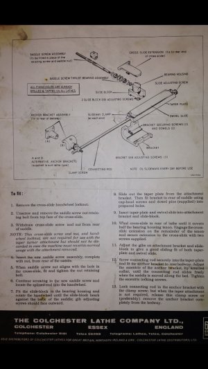

 Thanks Cheeseking - looks like my taper attachment is completely different - It is an Atlas Clausing model - not a Colchester. I'll post some pics as I work through it.
Well I got the spacer for the QCTP made and installed - should work fine.
My next step was to figure out what is going on with the cross slide play - I can move it about an 1/8" forward and back. I'm going to have to take it apart and see what is going on I think but before I did that I wanted to attack another project.
I wanted to install a cross slide threading stop but they are hard to come by. I decided I would buy one for a SB heavy 10 knowing it was not wide enough to fit the Clausing cross slide. I need to widen the dovetail in the stop and then drill and tap a hole in the cross slide. It seemed I should get this done before disassembling the cross slide because I would need to take it apart anyway for drilling and tapping.
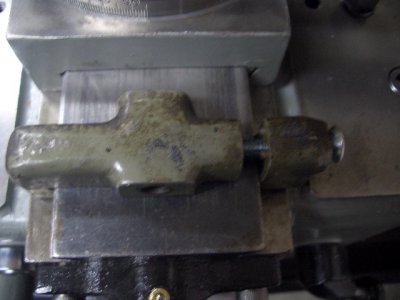
Here's the stop I bought
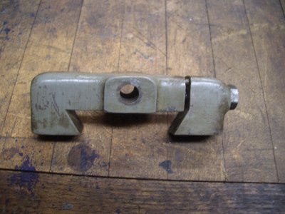
And its fit to the cross slide - there are two pins in the small section. In a perfect world the pins should touch the main body at the same time as the dove tail faces make contact. This is obviously not the case - yet. Also the hole for the cross slide attachment bolt should be centered on the cross slide. Again - not the case.
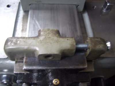
After some measurement I figured I needed to remove just under 1/4" from each side of the dovetail. I should note that I had a lot of guidance from a member of another forum (thanks Jeff). Based on his advice I decided to use a standard end mill to remove the bulk of the waste.
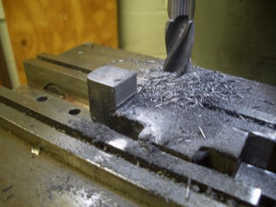
Then I used a 1" 60 degree dovetail cutter to reform the dovetail. I ran the Bridgeport in back gear at about 300 RPM and manually fed VERY slowly. Depth of cut was roughly .020". The milling went without incident except for me figuring out the correct feed direction - I had a second or two of back cutting (sorry Jeff - I know you warned me
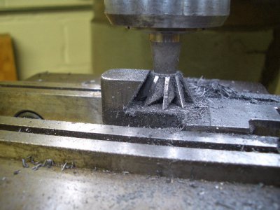
Here's the cross slide fit after completeing the first dovetail - you can see the gap is significantly reduced and the hole is roughly centered on the cross slide. Actually the hole is about 1/16" off - I didn't realizt that the dovetail cutter was not tall enough and was leaving a small ledge at the top of the dovetail. It was easy to file that off but by the time I discovered it I had gone too far.

I then proceeded to the small adjustable section and basically proceeded the same way except I didn't do the waste removal step but went right to the dovetail cutter.
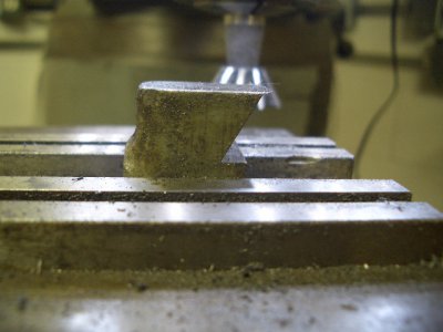
And the fit with both dovetails milled - both oins and the dovetail faces are touching
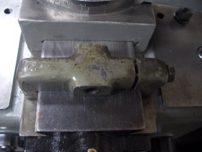
I locked the stop in place and used a transfer punch to mark the cross slide hole position and after applying some layout dye, marked the hole
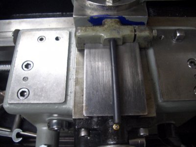
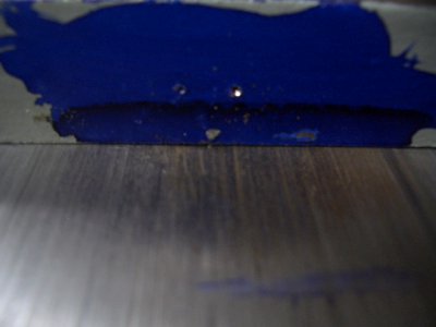
Now I need to remove the cross slide and compound and drill/tap the attachment hole. Then I can move ointo figuring out my cross slide slop problem.
Rick
Robert - I haven't drill/tapped the hole yet. The threading stops that I am familiar with operate using a screw threaded into the cross slide from the front. The screw slides through the stop. Whe the cross slide postion is estasblished (primarily used for getting back to the cross slide starting position when threading) the stop is clamped to the dovetail visa a side bolt. This allows you to back off the tool when a threading pass is complete, move the carriage for the next pass and reposition the cross slide to the original starting point before advancing the compound for the next pass. The bolt head in the stop acts as a limit for cross slide positioning.
Is there something about the Clausing design that doesn't require that bolt in the cross slide to act as a limit for positioning?
Rick
Is there something about the Clausing design that doesn't require that bolt in the cross slide to act as a limit for positioning?
Rick
OK - I did some investigation today to try and detemrine the source of the cross slide movement. I found two things. The cross feed nut was loose in the cross feed body - I tightened the set screw on that to stabilize it. I also found that the lower slide was loose in the support bracket (see parts list below). I tightened the set screws to adjust the gib until there is no movement at all in thelower slide. Those two things got me to about .015" back and forth movement of the cross slide when manually pushed/pulled.
Here's the parts list
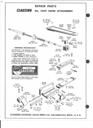
I noticed while investigating this that the taper slide block had a lot of movement around center slide. I think this is contributing to the cross slide movement. I also noticed that I have about .050" back lash in the cross slide feed. When I clamp the block down the back lash is cut in half which is about what I expected given the play in the splined feed screw and potential wear of the cross feed nut. The taper block is actually tilting up some due to the looseness of the fit around the center slide. This is not a dovetail slide - just a straight wall.
In thinking about this I realized I don't have a good handle on the operation of the taper attachment. I know the support bracket is bolted to the saddle and when in use the bracket is clamped to the bed so the saddle isn't moving at all. I also know that you adjust the center slide for the desired taper angle or inches per foot. What I don't know is what actually happens when in use? What parts are moving? I think the taper block slides along the center slide - is that the only moving part during operation? is the dovetailed lower slide just for positioning?
I asking because I'm not sure how tight a fit I canhave onthe lower slide and the taper slide block. I think the taper cutting action is the result of the lead screw telescoping out of the the the splined lead screw but I'm not sure of that. I would like to tighten the gib on the lower slide to allow no movement and shim the taper slide block to prevent movement thereby improving back lash. I don't anticipate cutting a lot of tapers so a little exta set up to undo these adjustments when cutting tapers is OK with me.
I appreciate any thoughts you may have
Rick
Here's the parts list

I noticed while investigating this that the taper slide block had a lot of movement around center slide. I think this is contributing to the cross slide movement. I also noticed that I have about .050" back lash in the cross slide feed. When I clamp the block down the back lash is cut in half which is about what I expected given the play in the splined feed screw and potential wear of the cross feed nut. The taper block is actually tilting up some due to the looseness of the fit around the center slide. This is not a dovetail slide - just a straight wall.
In thinking about this I realized I don't have a good handle on the operation of the taper attachment. I know the support bracket is bolted to the saddle and when in use the bracket is clamped to the bed so the saddle isn't moving at all. I also know that you adjust the center slide for the desired taper angle or inches per foot. What I don't know is what actually happens when in use? What parts are moving? I think the taper block slides along the center slide - is that the only moving part during operation? is the dovetailed lower slide just for positioning?
I asking because I'm not sure how tight a fit I canhave onthe lower slide and the taper slide block. I think the taper cutting action is the result of the lead screw telescoping out of the the the splined lead screw but I'm not sure of that. I would like to tighten the gib on the lower slide to allow no movement and shim the taper slide block to prevent movement thereby improving back lash. I don't anticipate cutting a lot of tapers so a little exta set up to undo these adjustments when cutting tapers is OK with me.
I appreciate any thoughts you may have
Rick
Well I think I answered one of my own questions. After some staring and thinking I suddenly realized that it is the lower slide that is clamped to the bed and the saddle slides in its dovetail so it has to be a sliding fit whe using the taper attachment. I don't think it matters for "normal"use. I'm still trying to wrap me head aroud how the cutting tool moves at an angle. More experimentation tomorrow. Its difficult to test this without the bed clamp parts but maybe I can rig up something for tempory playing around.
Rick
Rick
- Joined
- Oct 30, 2012
- Messages
- 960
The taper attachment definitely adds slop to the cross slide. I think its the nature of the beast when you add several more connection points each requiring some clearance to function smoothly. I found the extra slop unacceptable for normal use so I removed mine after trying it out to verify it actually worked. Fortunately I don't turn too may long slender tapers. For the most part the compound is sufficient.
The appropriate cliche seems like "I see said the blind man" - after focusing on the taper attachment today it all finally fell into place in terms of how it works. The key was understanding that it was the lower slide that gets clamped to the bed - not the support bracket. I was able to simulate the action and see what was happening. I think I got it 
As long as I was playing with the cross slide and taper attachment I figured it was a good time to pull the cross slide, remove the compound and drill/tap the threading stop hole. That went without incident - here's the stop installed
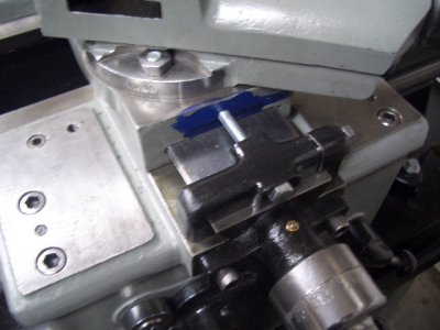
yeah I know - I still need to clean up the layout fluid .
.
Reassembly went well and gave me an opportunity to actually follow the directions for the taper attachment - what a unique concept. Once everythoing was installed I had smooth movement of the taper slides and a very limited amount of cross slide movement when pushed/pulled manually - maybe .015". Backlash in the cross slide is roughly .025" but I've been led to believe that with a taper attachment there will be more slop/backlash because of the added connection points. I'm going to leave as is for now.
I still need the taper attachment clamp parts - the lower clamp and rod are easy enough to fabricate and the I have a couple of leads on potential sources for the upper clamp. I still may need to fabricate that as well.
Rick
As long as I was playing with the cross slide and taper attachment I figured it was a good time to pull the cross slide, remove the compound and drill/tap the threading stop hole. That went without incident - here's the stop installed

yeah I know - I still need to clean up the layout fluid
Reassembly went well and gave me an opportunity to actually follow the directions for the taper attachment - what a unique concept. Once everythoing was installed I had smooth movement of the taper slides and a very limited amount of cross slide movement when pushed/pulled manually - maybe .015". Backlash in the cross slide is roughly .025" but I've been led to believe that with a taper attachment there will be more slop/backlash because of the added connection points. I'm going to leave as is for now.
I still need the taper attachment clamp parts - the lower clamp and rod are easy enough to fabricate and the I have a couple of leads on potential sources for the upper clamp. I still may need to fabricate that as well.
Rick
- Joined
- Dec 25, 2011
- Messages
- 10,511
OK. I went back and looked at the earlier photos to make sure but I didn't realize that the photos were of the front of the cross slide and not the rear. I thought that it was of the rear until I saw your most recent photo which shows the apron and compound. My cross feed stop goes on the rear.

