-
Welcome back Guest! Did you know you can mentor other members here at H-M? If not, please check out our Relaunch of Hobby Machinist Mentoring Program!
You are using an out of date browser. It may not display this or other websites correctly.
You should upgrade or use an alternative browser.
You should upgrade or use an alternative browser.
Logan 400. Headstock. (Total Logan 400 Rebuild)
- Thread starter mjhenks
- Start date
- Joined
- Dec 22, 2011
- Messages
- 715
I would say it is an adapter and should come out. What are the ID and OD of that piece?
- - - Updated - - -
This is from the Logan FAQ's:
[h=3]2.3. [FONT="]How can I add collets to this lathe? Which collets fit this lathe?[/FONT][FONT="][/FONT][/h] 2.3.. [FONT="]Logan[/FONT][FONT="] 11” and larger lathes came with a 2¼ - 8, L-00, L-0, D1-3 or D1-4 spindle noses. Logan supplied collet adapters for this spindle that fit 475 (also known as 5C) collets. The 5C collet is a very common size and is available in round sizes up to 1 1/16” and also in square and hex sizes. Decent quality imported round 5C collets sell for under $7 each and even less in sets.
Logan 9” and 10” lathes came with a 1½ - 8 spindle nose. Logan originally supplied collet adapters for this spindle that fit AC-30 (3AT) draw-in collets and AC-50 (W&S #1) collets. These are more limiting and less available than 5C collets, but equally precise and convenient.
You may be able to find used collet adapters to fit a Logan lathe at used machinery dealers. You can also make your own collet adapter. There were quite a few articles published in Home Shop Machinist and Machinist’s Workshop describing how to make a collet closer. Most show how to make a precision adapter that fits into the spindle nose and accepts a draw-in collet. With a draw-in collet adapter, a 10” Logan is limited to collets with a ½” bore, such as the 3AT collet. Larger lathes can accept 5C collets.
One article from 2004 shows how to make a collet adapter that fits over the spindle nose. This is a much more advanced project. Over-the-nose collet adapters allow a 10” Logan lathe to accept 5C collets because they don’t use the critical room inside the spindle nose.
You can buy new draw-in collet adapters made by Royal or new over-the-nose collet adapters made by Bison or Sjogren from Logan Actuator or other dealers.
The FAQ's can be found here: http://www.lathe.com/faq/index.html
Hope that helps.
Steve
[/FONT]
- Joined
- Jul 27, 2013
- Messages
- 295
Hey Matt;
It looks like an adapter in there. I'd just give it a few raps from the back side to see if it would pop out. Nothing to aggressive, just sharp solid taps. The guys on the list don't know your spindle is out, and so you can get a little more aggressive because the bearings are not an issue. Pulling is definitely in order if it does not come out with a few regular ball pein shots. You might also heat the spindle a tad to help expand it. Do support the spindle from the bearing shoulder, and very thoroughly, just in case you were inclined to rest it on the threaded end. I'll assume you are smarter than that. Nothing so far has shown me you aren't )
)
Logan will sell you a new dauber if you want that ultra original look. There was white lead down deep in the hole on mine when I cleaned it out.
I don't remember doing anything special to get my TS quill/screw apart. Remove the nut, handwheel, and the key. As far as I remember, the screw just came out, perhaps with only a tap.
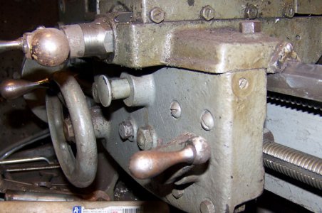
Don't know for sure, but on the 200 the dial goes where that set screw is in the end of the saddle pictured below. Yet another item my lathe is missing.
It looks like an adapter in there. I'd just give it a few raps from the back side to see if it would pop out. Nothing to aggressive, just sharp solid taps. The guys on the list don't know your spindle is out, and so you can get a little more aggressive because the bearings are not an issue. Pulling is definitely in order if it does not come out with a few regular ball pein shots. You might also heat the spindle a tad to help expand it. Do support the spindle from the bearing shoulder, and very thoroughly, just in case you were inclined to rest it on the threaded end. I'll assume you are smarter than that. Nothing so far has shown me you aren't
Logan will sell you a new dauber if you want that ultra original look. There was white lead down deep in the hole on mine when I cleaned it out.
I don't remember doing anything special to get my TS quill/screw apart. Remove the nut, handwheel, and the key. As far as I remember, the screw just came out, perhaps with only a tap.
Don't know for sure, but on the 200 the dial goes where that set screw is in the end of the saddle pictured below. Yet another item my lathe is missing.

- Joined
- Feb 5, 2014
- Messages
- 198
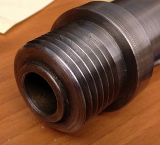
Mystery on the adapter solved. With a little persuasion it popped out. No wonder i always thought the center of the spindle was a tad small. Could never pass anything very large through. Now i have a good 3/4" diameter in there instead of 1/2".
FYI the OD at the nose was .941 & ID .685". Tail OD is .797 and ID is .556. It is about 2.5" long.
FYI the OD at the nose was .941 & ID .685". Tail OD is .797 and ID is .556. It is about 2.5" long.
- Joined
- Dec 8, 2013
- Messages
- 2,651
Mystery on the adapter solved. With a little persuasion it popped out. No wonder i always thought the center of the spindle was a tad small. Could never pass anything very large through. Now i have a good 3/4" diameter in there instead of 1/2".
FYI the OD at the nose was .941 & ID .685". Tail OD is .797 and ID is .556. It is about 2.5" long.
Sounds like an MT3 to MT2 reducer.
- Joined
- Feb 5, 2014
- Messages
- 198
Christmas was today. My spindle bearings arrived.
Main Bearing. Came with snap ring.

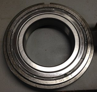
Back bearing
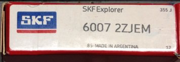
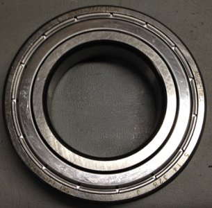
I must say they are both smooth as silk. Glad i did this as while my old bearings would have worked these are going to be really nice and smooth.
Otherwise i am finished painting accent colors and bolted the legs to the main casting. Now that the bearings are here i can start working on the headstock.
I also got the crossfeed gib re-ground How important are the divots for the gib screws? After ground they are a bit light. Not sure the best way to put them back in there.


Main Bearing. Came with snap ring.


Back bearing


I must say they are both smooth as silk. Glad i did this as while my old bearings would have worked these are going to be really nice and smooth.
Otherwise i am finished painting accent colors and bolted the legs to the main casting. Now that the bearings are here i can start working on the headstock.
I also got the crossfeed gib re-ground How important are the divots for the gib screws? After ground they are a bit light. Not sure the best way to put them back in there.


- Joined
- Feb 5, 2014
- Messages
- 198
Did some preliminary assembly last night.
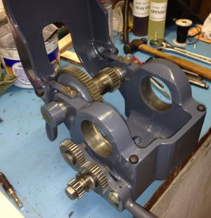
What do you all use to keep the bare metal parts from rusting again? I live near the ocean and this lathe will not be used. (maybe a few times a month) Besides coating everything with oil and covering the lathe what other tricks are out there? Really questioning if i should have all the hardware plated. that would leave just the gears and ways unprotected which oil should solve.
OK.....
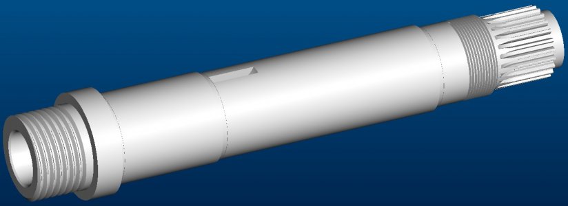
Getting ready to put the spindle back together. Man how i wish i took better notes and pictures. I was relying on the factory parts book as my guide but when it comes to the spindle it is not detailed enough. Thought there was a cross section in there but it is the QCGB.
So, the spindle assembly. Lets figure this out step by step.
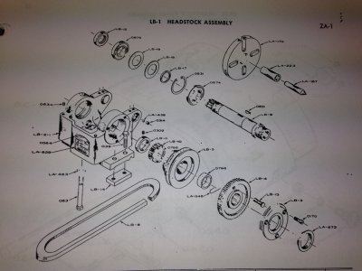
It is clear that bearing 0674 goes into the headstock with the clip facing out. That bearing therefor has to press onto the spindle first. Don't forget to only press on the inner race. Otherwise you will damage the bearing
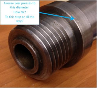
The question is the grease seal. (LA-672) i think it presses to the outside of the nose of the spindle. (Just behind the chuck thread) How far does it go on and i think this can only go on after the spindle is installed and the nose bearing cover is installed. (LB-3)
Install the rear bearing "C" clip. (0931)
After the nose bearing is installed, pass the spindle through the headstock front and slide on the following in this order:
Bull gear assy. (LB-4)
Spindle Pulley. (LB-5)
Belt. (LB-6)
Spindle Gear. (LB-10)
Collar. (LB-11) (Leave set screw loose)
Spacer. (LB-17)
Belleville Washer #1. Concave toward nose bearing. (LB-16)
Belleville Washer #2. Concave toward tail bearing. (LB-16)
Press or otherwise install the nose bearing into the housing and install the nose bearing cover and screws. I expect this to be a transition or slip fit. (Now comes the grease seal????)
Next is the tail bearing. bearings should not be double pressed. Since there is a take-up nut coming next the bearing cannot press to the shaft but could press to the housing. That would be interesting but since i did not press this bearing off i expect this to be a double slip system.
Once the bearing is installed then comes the Take-up nut. (LB-12) The million dollar question how much torque the take-up nut requires.
The other question is how tight should the belt be? I have always thought the belt was too tight. I realize you can adjust the through on the motor tensioner but in general how tight should the belt be? I have seen them tight and what i would consider loose. How much up/down should a properly tentioned belt move? (One side)
Recap...
Where did i go wrong in my figuring?
How do you protect your bare metal?
What is the take-up torque
How tight should the belt be?
Teaser.... The post office dropped off a couple of packages last week. One was about 30" long and the other heavy with very dirty content.... I will more than likely start a new thread for that.....
Matthew


What do you all use to keep the bare metal parts from rusting again? I live near the ocean and this lathe will not be used. (maybe a few times a month) Besides coating everything with oil and covering the lathe what other tricks are out there? Really questioning if i should have all the hardware plated. that would leave just the gears and ways unprotected which oil should solve.
OK.....
Getting ready to put the spindle back together. Man how i wish i took better notes and pictures. I was relying on the factory parts book as my guide but when it comes to the spindle it is not detailed enough. Thought there was a cross section in there but it is the QCGB.
So, the spindle assembly. Lets figure this out step by step.

It is clear that bearing 0674 goes into the headstock with the clip facing out. That bearing therefor has to press onto the spindle first. Don't forget to only press on the inner race. Otherwise you will damage the bearing
The question is the grease seal. (LA-672) i think it presses to the outside of the nose of the spindle. (Just behind the chuck thread) How far does it go on and i think this can only go on after the spindle is installed and the nose bearing cover is installed. (LB-3)

Install the rear bearing "C" clip. (0931)
After the nose bearing is installed, pass the spindle through the headstock front and slide on the following in this order:
Bull gear assy. (LB-4)
Spindle Pulley. (LB-5)
Belt. (LB-6)
Spindle Gear. (LB-10)
Collar. (LB-11) (Leave set screw loose)
Spacer. (LB-17)
Belleville Washer #1. Concave toward nose bearing. (LB-16)
Belleville Washer #2. Concave toward tail bearing. (LB-16)
Press or otherwise install the nose bearing into the housing and install the nose bearing cover and screws. I expect this to be a transition or slip fit. (Now comes the grease seal????)
Next is the tail bearing. bearings should not be double pressed. Since there is a take-up nut coming next the bearing cannot press to the shaft but could press to the housing. That would be interesting but since i did not press this bearing off i expect this to be a double slip system.
Once the bearing is installed then comes the Take-up nut. (LB-12) The million dollar question how much torque the take-up nut requires.
The other question is how tight should the belt be? I have always thought the belt was too tight. I realize you can adjust the through on the motor tensioner but in general how tight should the belt be? I have seen them tight and what i would consider loose. How much up/down should a properly tentioned belt move? (One side)
Recap...
Where did i go wrong in my figuring?
How do you protect your bare metal?
What is the take-up torque
How tight should the belt be?
Teaser.... The post office dropped off a couple of packages last week. One was about 30" long and the other heavy with very dirty content.... I will more than likely start a new thread for that.....
Matthew


- Joined
- Jul 27, 2013
- Messages
- 295
Got a couple minutes at lunch. My experience is with the 200, so there may be some difference in how a 400 goes together. It is my assumption that there is NOT a great difference, at least in terms of process.
<<What do you all use to keep the bare metal parts from rusting again?>>
Oil is all I know. Messy, but it works. coat it good when not in use, wipe it down to use it, then oil it up again afterwards.
<<That bearing therefor has to press onto the spindle first. Don't forget to only press on the inner race. Otherwise you will damage the bearing>>
The bearing should be a close hand slip fit onto the spindle AFAIK. if it is not you need to polish the spindle a bit. The bearings should be a slight interference fit into the headstock. You should not have to press them in, although that certainly does not hurt. I have removed & installed mine numerous times with nothing more than a rawhide mallet that weighs VERY little.
<The question is the grease seal. (LA-672) i think it presses to the outside of the nose of the spindle. (Just behind the chuck thread) How far does it go on and i think this can only go on after the spindle is installed and the nose bearing cover is installed.>>
That is a bearing seal COVER. It goes on LAST, after the bearing cap, and basically just goes where it ends up. Tap it in until it bottoms out and there you are.
<<Next is the tail bearing. bearings should not be double pressed. Since there is a take-up nut coming next the bearing cannot press to the shaft but could press to the housing. That would be interesting but since i did not press this bearing off i expect this to be a double slip system.>>
On the 200, the rear bearing goes in after all the central spindle bits, and sort of just goes where it ends up. The spacer collars that fit on either side of it will press it into its final position between them. The inner of these spacers hit a shoulder on the spindle, and the bearing and outer spacer sleeve press it all together. Things look a bit different from looking at the 400 schematic, but its hard to tell, especially without the part description. However, it should all go together by hand with little difficulty. Light tapping is all you should have to do. That's my assumption.
<<Once the bearing is installed then comes the Take-up nut. (LB-12) The million dollar question how much torque the take-up nut requires.>>
Tight enough to stay tight enough! I'm not aware of a spec. It does NOT need to be cranked down with a pipe or anything. As long as the nut and spindle gear stay in place, it's tight enough.
<<The other question is how tight should the belt be? I have always thought the belt was too tight. I realize you can adjust the through on the motor tensioner but in general how tight should the belt be? I have seen them tight and what i would consider loose. How much up/down should a properly tentioned belt move? (One side)>>
There are two aspects to this. Tight enough to drive is tight enough. So tight that it causes excessive bearing load or drag is too tight. It is a bit of a moving target until the new belt breaks in. Too loose can also cause belt flop which makes things shake when the belt flaps. When everything settles in and has some miles on it, tight enough not to slip easily, but not flap either, is right.
- Joined
- Feb 5, 2014
- Messages
- 198
Thank you Redlineman.
Small update. Motor mount assembled. Motor is already mounted and i tested out how well the jackshaft spins. Alot quieter now that the shaft actually fits the bushings. I also realize that i will have to slide out the shaft to install the drive belt later on.
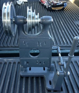
Also got the main bearing pressed on today and made new pivot pins for the cover.

Small update. Motor mount assembled. Motor is already mounted and i tested out how well the jackshaft spins. Alot quieter now that the shaft actually fits the bushings. I also realize that i will have to slide out the shaft to install the drive belt later on.

Also got the main bearing pressed on today and made new pivot pins for the cover.


