How much air can a fly cutter cut?

dave2176

Active User
Registered
Joined
Aug 20, 2013
Messages
909
If I only had a 2.5" head fly cutter could it be used to pretty up 1.5" wide steel? That would be at least a 3" swing with a very small tip sticking out. Too much air or doesn't it matter to them? I could use 1" end mill and make 2 passes but then you end up with 2 lines of swirl marks.

Thanks for your help,
Dave
 
Doesn't matter, in a general statement. Caveats: the larger the swing, the more pronounced any out of true spindle effect will be. Also, run it offset so that the approach presents the cutting edge as negatively as possible to the workpiece.
 
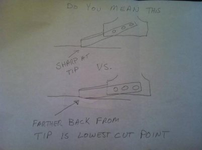
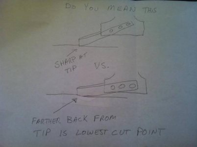
I may end up drawing pictures of this. Hard to put into words, but I'll try. If you set the cutter over the work enough, when the bit first touches the material, the very tip....the most fragile point of the tool makes first contact, bearing the brunt of the impact on a small area. If you set it to the other extreme, you avoid that and have a broader first contact point. In fact, you can make the first contact point away from the very tip, thus protecting the delicate point.

May be best illustrated if you think of just cutting half of the swept diameter of the bit, or less....say, 25%. What part of the bit hits first? Then go the other way, bury it in width. Now what part hits first?
 
OK ,it took me a few readings to understand your question:
Radial engagement, right?
Rule of thumb, its 66% ; NEVER at 50%; go to 25% or 100% if needed.
Radial engagement, will also dictate pressure between tool & workpiece. Less pressure, less machine / part movement.
Then again, what are you trying to do?
Prettying up a piece of steel; Dimensional? Surface finish wise?
If its surface finish, what type of machine do you have? any loose in the gibbs?
How rigid is your mill? ie climb milling vs conventionnal milling
Have you trammed your mill? (giving a slight angle on a leading edge, can "scallop" surface finish between multiple passes, helping in blending the passes.

I know I ask a lot of questions, but its in order to give you the best answer I can...
Fred
 
Last edited:
Tony,
Could you please draw those pics so I can follow what your saying. I read and reread the explanation but just cannot visualize what you are describing. I surely would like to know how to do this too.

Bob
 
I'm really enjoying where this thread is going. Thank you all for jumping in.

I originally asked the question because I wanted to clean up saw marks on a piece before I continue with the actual machining to shape the piece. No real need to change its dimensions. If I use an end mill the piece is smooth (my mill is trammed well with no measurable nod) but you can see each cuts swirl marks. I was wondering if I can use a 2.5" fly cutter to clean up the saw marks on a 1.5" x 8" piece. That would mean it would be in air at least half the time depending on how far the cutting edge protrudes from the fly cutter.

Tony answered the question by saying that the air time doesn't really matter but then qualified it by saying that it needs to be offset so you present a "negative" edge so it doesn't hurt the cutter. Honestly, that stumped me. Thinking about it I came up with this.
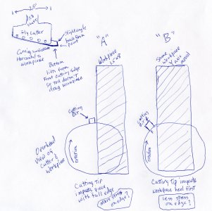
JPG030a.jpg

Top left shows the cutter ground and inserted. If I understand other threads correctly it is ground horizontal to the mill table? Also the trailing side of the cutter needs to angle up a degree or two so it doesn't drag after the cut is made. Should the tip end angle back from the bottom so it presents a sharp edge? What about the trailing edge of the end of the bit so it doesn't drag as well?

"A" and "B" show two of many ways the bit can be presented. We are looking down on the work. X axis follows the length of the piece, Y of course the short width. The piece is clamped in a vise. It seems to me that "A" would cause greater stress than "B" on the cutting edge. Would it be better to move the Y axis further to the right of "B" in the picture?

In woodturning a negative edge or negative rake would point the bit down from the centerline, even if you engage the center of the workpiece. Similar on metal lathe tools, right? Still having trouble putting that into this perspective on a mill where the tool is turning instead of the work piece.

Thanks again for all your help,
Dave
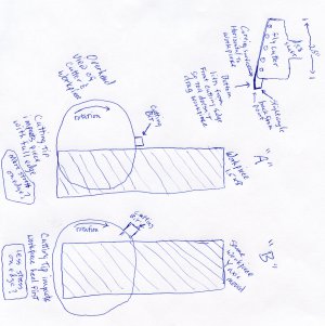
JPG030.jpg JPG030a.jpg
 
I'm really enjoying where this thread is going.

Me too! but I'm not really buying the advice yet.

Dave, in your interpretation of what he's saying, it really only works for the first rotation of the tool. After that, the tool advances into the work at the next position for the next pass of the cutter. Leading with the lowest edge.

Correct me if I am wrong, but the only thing being done by having the center of the cutter rotation moved off center farther, is that more of each pass is transitioned to climb cutting during the tool's pass. If that was the answer, why not just feed the work through on the climb side of the cutter?
 
Skills,
Can't begin to correct you. So "A" is climb milling which can be problematic because of backlash. What about coming from the opposite side rather than down the center like "B" shows?

I was just looking at Glacern face mills and they mention positive geometry and you can see the toe of the cutter sits forward. To get to a negative presentation on the fly cutter do I need to grind the face of the cutter so the edge sits back?

Dave
 
Back
Top