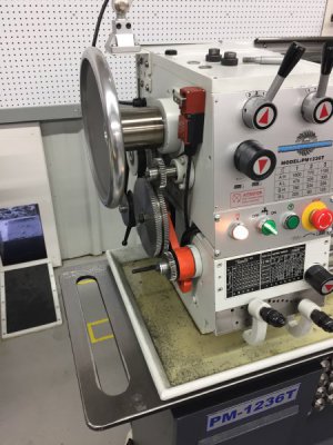
Setting-up the PM 1236-T Lathe

Larry42, your project makes mine sound simple. Your idea of a test piece for fitting is a good one, I wish I had thought of that. Also wish the spindle was longer and extended beyond the cover on my lathe. As you will see it would have made things easier for me.
 
My lathe came with a built in coolant system. Have never used it. Didn't want to deal with the mess. I occasionally use some SS, have never used titanium. At my shop acid brushes are used for various things and bought by the gross, dirt cheap. They are my lube/"coolant pump."
Todays project was turning some cypress balusters for my front porch. Was going OK until the hydraulic copy lathe tool refused to retract. Guess that will be tomorrows project, taking apart the valve system.
 
Shrink fitting the wheel hub to the adapter.

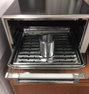
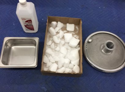
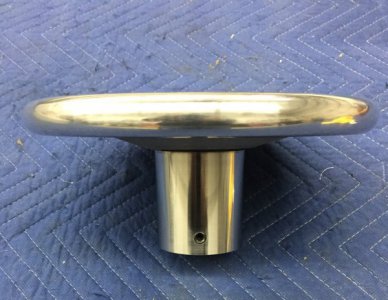
This seemed like a good option to me. It would put the pieces together tightly and permanently without fasteners to loosen or catch onto something while turning. There are some complex formulas for determining the amount an alloy a certain size and configuration will expand on heating and shrink on cooling but I decided to take direct measurements instead. I heated the adapter to 450 F and took multiple measurements and averaged them. The ID of the adapter expanded by 0.005”. I cooled the hub of the hand wheel in dry ice and isopropyl alcohol to the temperature of Milwaukee these days, -107 F. It’s diameter contracted by 0.003”. So there was a difference of 0.008” between their room temperature dimensions and their dimensions when heated and cooled. Most sources that I read gave a rule of thumb of .001” difference in the two parts per inch of diameter so I bored the ID of the adapter to 0.004” smaller than the room temp diameter of the handwheel hub. Remember the OD of the adapter is 2-3/4” so thIs should give me plenty of compression. Too much and I could crack the pieces. I then heated the adapter and cooled the handwheel hub. I dropped the adapter on to the hub and almost instantly they were bound together; no time for repositioning. It was impressive.

6D51EE8B-908E-4430-9761-4922FC574C95.jpeg. F8164AA6-F71C-4AB2-B277-0ACD24C53110.jpeg

CFAF6D58-2458-4DFF-82B1-F7E9BFEF6E9F.jpeg. CE199B6E-B0F8-4A84-A7A2-5AA79BE66FA6.jpeg

BAC85BBC-C5DD-4A79-A91F-F31DC634DC07.jpeg

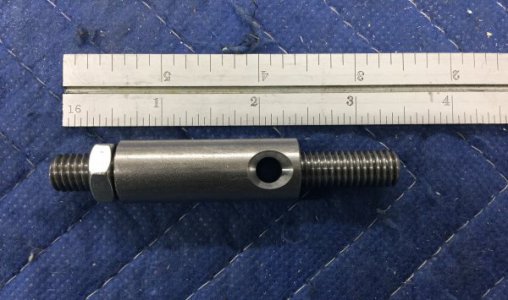
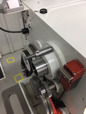
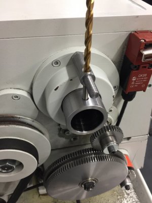
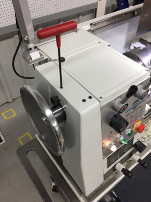
The next and final step was to create a way I could access the set screws to the adapter while the cover was in place. To do this I made a new larger diameter, 5/8”, upper post for the cover with a hole in it and then drilled and tapped a hole in the top of the cover so an Allen wrench would then drop down through the hole, then through the hole in the new post and would be guided to the Allen screws on the adapter. When the hole was not being used it was cover with an Allen screw that uses the same size Allen wrench.

25B35DAE-B336-4548-9272-32A7C5CAD28D.jpeg. B9184ED7-F214-48E2-AAA7-BB07CF3AD70A.jpeg

09B1AA00-148A-4286-B1C5-DD9561A0834E.jpeg. 60443E2E-0D33-4758-889D-3917CD0E6442.jpeg

That’s it for the headstock handwheel.
 
I am going to skip ahead to part E under Miscellaneous which is installing Oil Drain Stopcocks. I don’t have access to the information I need for the three short sections preceding this so I thought I would continue to move forward and then circle back around to do these skipped topics later.

V. Miscellaneous
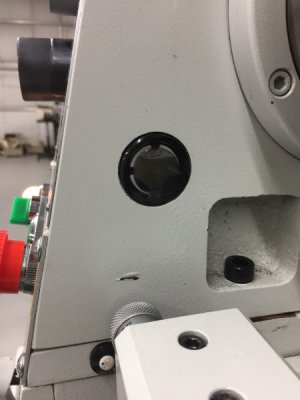
E. Oil Drain Stopcocks- I have had the lathe for almost a year now and noticed a while ago that the original oil in the site gauge was getting dirty, so I decided to change the headstock oil and also the oil in the apron gearbox while I was at it. The PM Manual suggests that to do this for the headstock gearbox you should remove the cover, take off the change gears, hold a paper channnel in place, remove the drain plug and let the oil run down the channel into a bucket on a stool. For the apron, it is a bit less involved and one is instructed to simply remove the drain plug, let the oil drain and then refill. I guess the oil is to go into a shallow pan and then caried away to where you dispose of your waste oil. Not a big deal for either but I thought I would try to make it a bit easier and less messy so I would be more likely to change the oil regularly.

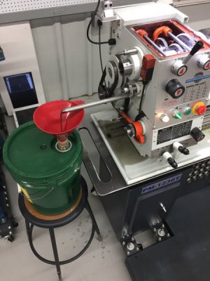
This is how I changed the headstock oil the first time. The pipe is a bit of an improvement over holding a paper channel against the side of the gearbox while the oil drains but you can still see dirty oil pretty much everywhere:
0CE56268-774B-4CA6-A59B-35A817DBB8F7.jpeg

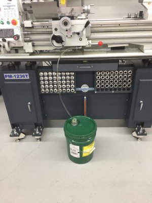
I think it is an easier and cleaner process after the Stopcocks are installed:
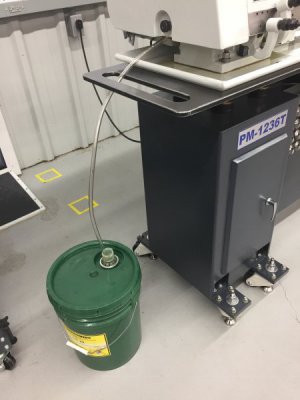
A10EE208-39A5-402F-8929-47C5E30B40A3.jpeg. 34993BE0-4F06-4682-8AF7-F8486405F5CB.jpeg

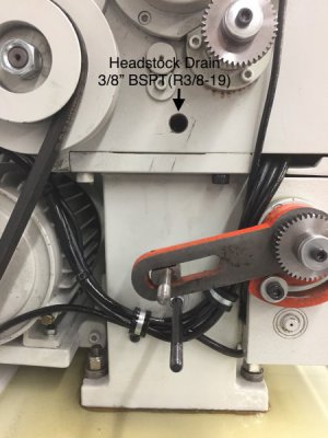
The Headstock Oil Drain Stopcock- First of all, be careful of the threads. Like the coolant guard there are British, not metric, threads here. The drain plug is 3/8”-19 BSPT(aka R3/8-19) so at some point an adapter is need if you are going to go to US standard pipe thread such NPT or NPTF.

Here is the kit view of what you will need to start this job and a view of the location of the drain with the external change gears removed:
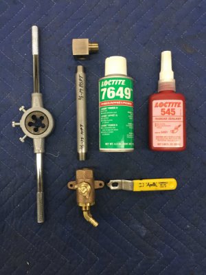
32493A44-B3B9-4943-9209-A01C81D9E68E.jpeg. A788D5FB-0DE6-4E0D-8B2B-0EFD445AE132.jpeg

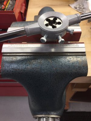
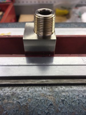
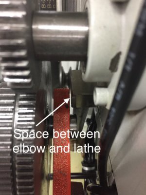
The first thing to attach is the 90 degree elbow(3/8” BSPP F x BSPT M, MC 4860K428). There is a very tight clearance here, in fact, I needed to reduce the diameter of the thread a bIt( I used a compressed die and re-threaded) to get the elbow to go in far enough that it would not hit the orange arm on the lathe:
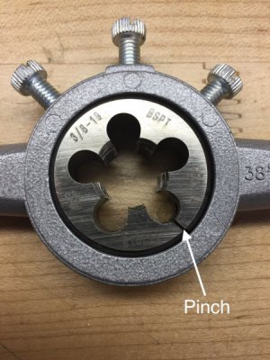
971D3262-A82A-4648-B66A-6EF11963E13E.jpeg. E9FB91D5-3668-47A2-B4D0-9E2C82EED57F.jpeg

54DA4EEA-8370-473B-8567-5043ED652B95.jpeg. BEFC7F20-49CD-4796-A0B1-93037F6F5F82.jpeg

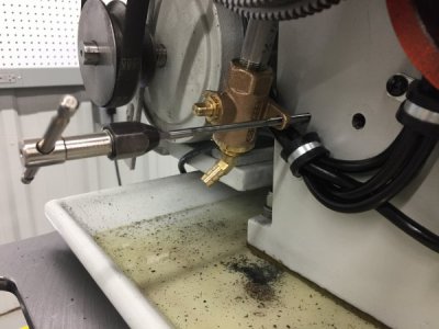
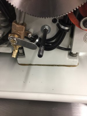
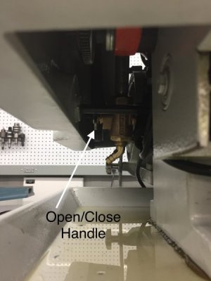
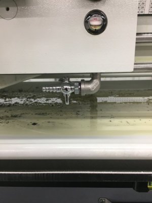
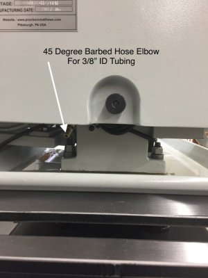
Next, I attached a 6” stainless pipe(3/8” BSPT x 3/8” NPT, MC 2427K333), 3/8” NPT bronze shut-off valve(Canbraco(Appollo)78-250-10) and 45 degree 3/8” NPTF barbed fitting for a 3/8” ID drain hose(MC 53525K48). I shortened the stainless handle so it would not hit the post that holds the cover. I used pipe sealant on all joints:
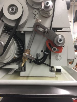
465D9243-7DC7-411E-BA0F-8873EB5778BF.jpeg

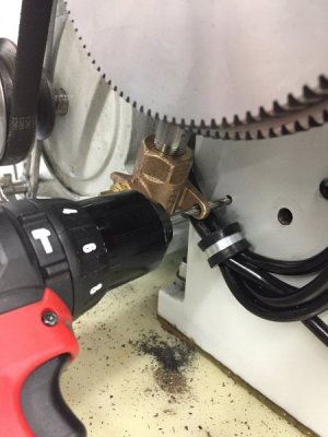
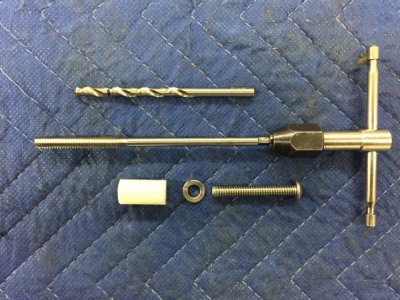
I removed one of the feet on the valve, drilled the remaining foot out to 1/4”, drilled and tapped the lathe base to 1/4”-20 and fastened the valve with a socket head cap screw and 1” nylon stand-off:
625AEACE-7B98-4F3E-B8D8-9C2BB7F88925.jpeg. D5E414A3-2ED2-416F-AABB-4B0B57BAC046.jpeg

0473572E-8738-447B-8B41-458D0E6CE744.jpeg. A55F955F-46DE-4C74-B227-A3A0FB3ECE7E.jpeg

This set-up allows me to easily drain the oil without taking the cover off which is especially nice for me since I have the headstock handwheel that I would need to remove first:
0F77F38E-7764-48F0-B9A0-45CD91E64849.jpeg. 5757E2C1-3AA9-4C8B-9593-0818796079D1.jpeg

A10EE208-39A5-402F-8929-47C5E30B40A3.jpeg

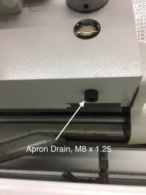
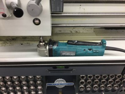
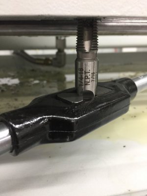
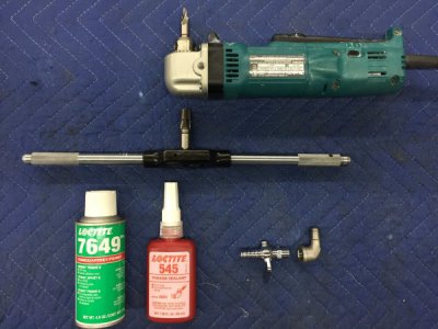
The valve on the apron gear box was also pretty straightforward. I removed th M8 x 1.25 drain plug screw, drilled it out to 7/16” using a short drill bit and an angle drill. I then tapped it to 1/4-18 NPT. I then put in a stainless 1/4” NPT 90 degree adapter(MC 4452K472) and a 1/4” NPT on/off valve(MC 8179K74) with a hose barb for 3/8” ID tubing(like the headstock drain):
1B30D56B-BC72-448B-AF31-E2934F0BC31F.jpeg. 781D8938-3A57-4B5B-82A6-AEBB680783F7.jpeg

F6CD09C6-82EA-4E98-9F50-DEFF9EDB10FD.jpeg. D039C2A4-1C40-4ABC-B472-842D411F7ECA.jpeg

7990675F-74DF-4ABB-B593-E7C2812FE4F7.jpeg

34993BE0-4F06-4682-8AF7-F8486405F5CB.jpeg

That’s it.
 
very nice idea! I was thinking along the same lines, but you have developed into a way better idea than I came up with!
 
I wonder if the will make using the change gears slower. I'll bet you have figured out how to minimize the change over time. Most of the equipment in my shop is metric and I do repairs for them so need to use the change gears. Improving the oil drain has been on my todo list for quite some time. British pipe threads are standard on all my European equipment. Hadn't thought about it on Chinese.
The oil fill and drains, on mine, are as awkwardly deigned as on yours. The head stock drain is partly behind the drive belts, the gear case fill is very close to the change gears. The apron drain is on the bottom like yours. Next time I have to do oil changes I'll fix them.
 
very nice idea! I was thinking along the same lines, but you have developed into a way better idea than I came up with!

Thanks Dabbler, I bet your idea works well also. Fortunately, there are many ways to accomplish these things, that’s the fun of it!
 
I wonder if the will make using the change gears slower. I'll bet you have figured out how to minimize the change over time. Most of the equipment in my shop is metric and I do repairs for them so need to use the change gears. Improving the oil drain has been on my todo list for quite some time. British pipe threads are standard on all my European equipment. Hadn't thought about it on Chinese.
The oil fill and drains, on mine, are as awkwardly deigned as on yours. The head stock drain is partly behind the drive belts, the gear case fill is very close to the change gears. The apron drain is on the bottom like yours. Next time I have to do oil changes I'll fix them.

Larry42, it seems like the drain systems are a bit of an afterthought for the manufacturers. It would be a nice thing if PM offered something like this as an accessory kit or even a standard feature on the 1236-T.

I went through the various gear configurations after installing the drain system and all was OK.

It’s funny how a small impediment to doing something, like taking the cover and change gears off and well, cleaning up a mess, can dramatically affect how often you do something. I waited too long to change the oil the first time. I think this set-up will help me keep up with the oil changes.

I hesitate to show you this, but before I changed the oil I ran the lathe for about ten minutes to warm-up the oil. This is the oil in the site glass just prior to the change:

21576BB1-9AA9-4785-85E0-B81E9F296822.jpeg

Ugh
 
So how many run hours do you get to a change of oil?
 
So how many run hours do you get to a change of oil?

Firstgear, this was the first oil change. I got the lathe about a year ago, light use. Do you have any recommendations regarding oil change intervals.

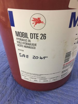
This is what I used:

23D5A77A-263F-4FB2-ABD6-4EDB18D7577E.jpeg
 
Back
Top