-
Welcome back Guest! Did you know you can mentor other members here at H-M? If not, please check out our Relaunch of Hobby Machinist Mentoring Program!
You are using an out of date browser. It may not display this or other websites correctly.
You should upgrade or use an alternative browser.
You should upgrade or use an alternative browser.
Setting-up the PM 1236-T Lathe
- Thread starter Titanium Knurler
- Start date
- Joined
- Jan 18, 2018
- Messages
- 314
- Joined
- May 10, 2017
- Messages
- 1,199
Quick question for you, is there a to time/length limit to a thread on HM?
Nope TK, keep it rolling. I’m finding you ideas very interesting
- Joined
- Jan 18, 2018
- Messages
- 314
OK, Z2V, as long as I know someone is out there I will keep going.
What I plan on doing next is a couple of short sections(minor electrical stuff and then building a platform). I also forgot to take time to indicate what I would do differently if I were to do these things again and to make recommendations to PM and LD so I thought I would briefly catch up on that then proceed with the outline.
What I plan on doing next is a couple of short sections(minor electrical stuff and then building a platform). I also forgot to take time to indicate what I would do differently if I were to do these things again and to make recommendations to PM and LD so I thought I would briefly catch up on that then proceed with the outline.
- Joined
- Nov 23, 2014
- Messages
- 2,611
Hi Titanium Knurler,
Still really interested in your string. You brought up some math I hadn't through about since around spring term of 1980 . . . Wow, have I forgotten a lot! Makes me feel bad that I haven't checked my lathes' leveling in a few years (I haven't moved them during that time). Great work you're doing here.
Bruce
- Joined
- Jan 18, 2018
- Messages
- 314
II. Set-up
C.) Elecrical
Short section here. Three items: 220v single phase outlet, power cord and light. I will show the wiring of the coolant system under that section.
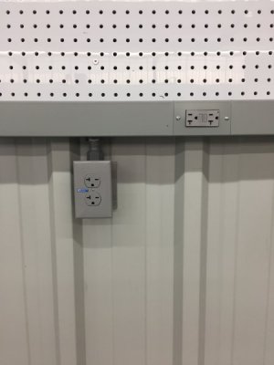
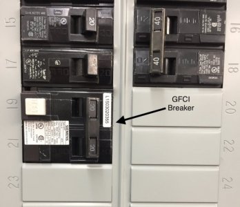
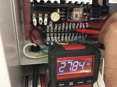
I did not have a 220v, single phase outlet at the lathe location but I did have a wiremold raceway that I had installed for 110v. I ran about thirty feet of AWG 12 wire. This gave a voltage drop of slightly less than one volt. I installed a 220v GFCI breaker at the service panel.
 .
. 
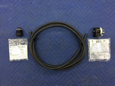
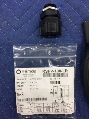
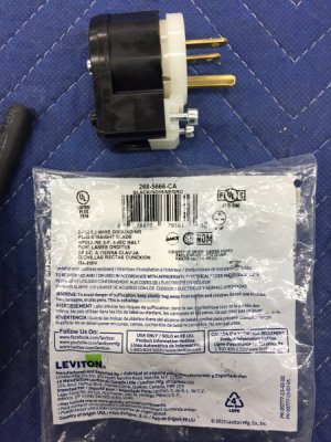
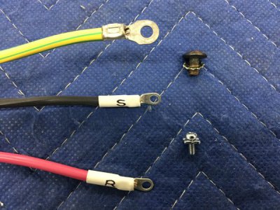
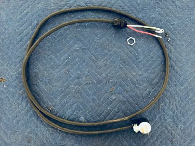
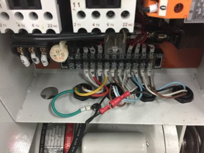
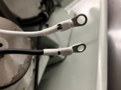
My lathe did not come with a power cord so that needed to be wired. I used AWG12 harsh environment cable from Mcmaster-Carr industrial supply which is where I get the majority of my supplies. A really great company to deal with; they are just down the road in Chicago and often if I order in the morning I will usually get the item the same day. Some more pictures:
 .
. 
 .
. 
 .
. 
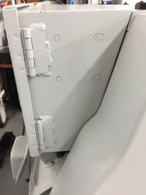
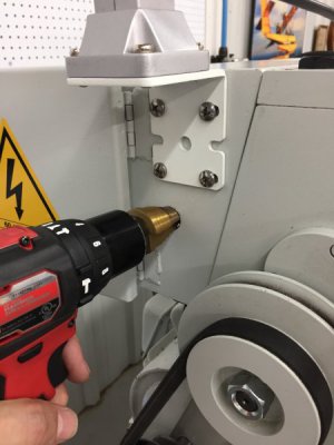
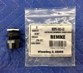
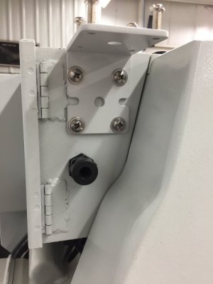
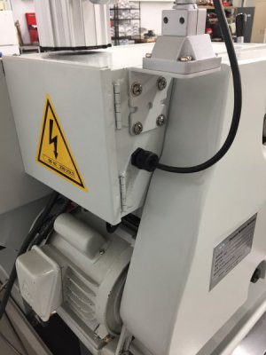
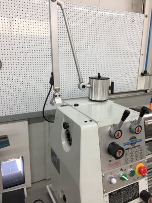
The light is supposed to attach to the splash guard by the headstock but I was planning on installing a coolant and guard system and it was in the way there. Also, I didn’t want it to get splashed so I moved it over to the electrical box behind the headstock. The bracket that holds the light was a different color than the back lathe/splash so I painted it with some of the extra touch up paint I had. More pictures:
 .
. 
 .
. 
 .
. 
 .
. 
That’s it for electrical, except for the coolant system, and there was no math!
C.) Elecrical
Short section here. Three items: 220v single phase outlet, power cord and light. I will show the wiring of the coolant system under that section.
I did not have a 220v, single phase outlet at the lathe location but I did have a wiremold raceway that I had installed for 110v. I ran about thirty feet of AWG 12 wire. This gave a voltage drop of slightly less than one volt. I installed a 220v GFCI breaker at the service panel.
 .
. 
My lathe did not come with a power cord so that needed to be wired. I used AWG12 harsh environment cable from Mcmaster-Carr industrial supply which is where I get the majority of my supplies. A really great company to deal with; they are just down the road in Chicago and often if I order in the morning I will usually get the item the same day. Some more pictures:
 .
. 
 .
. 
 .
. 
The light is supposed to attach to the splash guard by the headstock but I was planning on installing a coolant and guard system and it was in the way there. Also, I didn’t want it to get splashed so I moved it over to the electrical box behind the headstock. The bracket that holds the light was a different color than the back lathe/splash so I painted it with some of the extra touch up paint I had. More pictures:
 .
. 
 .
. 
 .
. 
 .
. 

That’s it for electrical, except for the coolant system, and there was no math!
- Joined
- Jan 18, 2018
- Messages
- 314
Hi Titanium Knurler,
Still really interested in your string. You brought up some math I hadn't through about since around spring term of 1980 . . . Wow, have I forgotten a lot! Makes me feel bad that I haven't checked my lathes' leveling in a few years (I haven't moved them during that time). Great work you're doing here.
Bruce
Thanks Bruce, very happy you are interested in the string. Sorry about the math but I was curious and thought I would pass the result along. Really a coincidence that I found a math professor that was a machinist. I wouldn’t feel too badly about not leveling your lathes recently. I bet you are getting good results and this really does seem to introduce only a very small error. When I used Dr Jackson’s formula for my lathe I get an error of 0.00000025”. I am not even sure what you call that number? Twenty five ten millionths? Whatever it is, it is good enough for what I do.
Take care
Jester966, think of it this way. Say you are a machinist on a battle ship...Think of the plate on the mobile base as the battle ship.
I am well aware of the concepts of leveling a lathe, but didn't realize you had the "base plate" between the lathe and the stand.
...I don’t think there is anything I can do to make it rigid so it will always twist when it is moved.... so I isolated the two, somewhat, from one another. The stand can twist when moved while the lathe stays rigidly attached to it’s baseplate...
This makes sense, and was good thinking. I suspect the 1/2" base plate twists just as much (and likely more) than the lathe bed during the leveling process. This isn't a necessarily problem though since once the lathe is leveled, it and the plate float independently of the stand.
Of course this setup will certainly not provide anywhere near the rigidity that a typical footing to the concrete floor does. You're not going for rigid though - your going for mobile, and I think your solution is quite good.
- Joined
- Jan 18, 2018
- Messages
- 314
"I am well aware of the concepts of leveling a lathe, but didn't realize you had the "base plate" between the lathe and the stand."
Jester966, very much hope I did not offend you with my simplistic battle ship story. If I did I apologize.
I think you are correct when you state that the plate probably twists with leveling. I considered this when thinking about the plate and decided that even if the plate did twist the two would reach a stable equilibrium.
- Joined
- Jan 18, 2018
- Messages
- 314
II. Set-up
D.). Platform
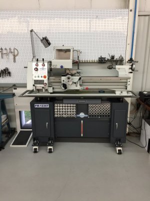
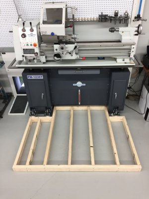
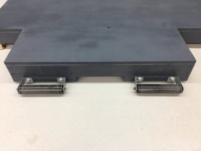
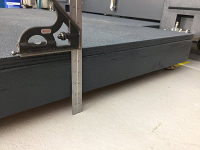
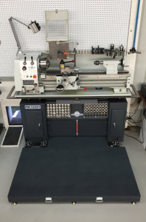
The stand gained 3-1/2” with the outriggers and casters and another 3-1/2 inches with the machine mounts and plate. I am not sure what a normal lathe height is but it seems like they are often pretty low. The PM Manual lists the spindle height at 45” above the floor, I was at 51”, so I decided to build a platform.
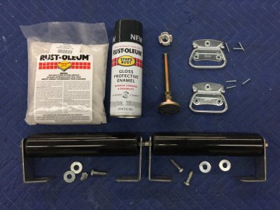
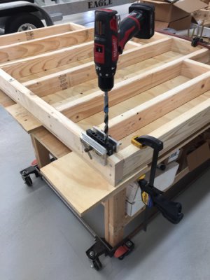
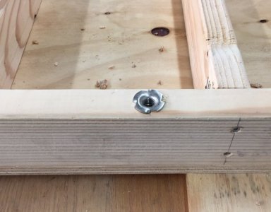
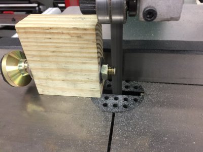
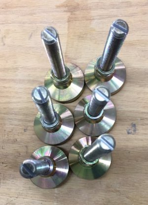
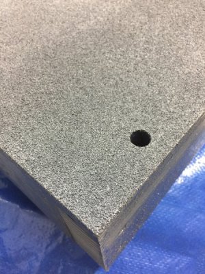
I built a framework using 2x4s, and covered it with 3/4” plywood, added some leveling feet and painted it. I sprinkled an anti-skid coating(like sand or pumice) on the fresh paint then painted it again to get a surface about equivalent to 50 grit sandpaper. I added handles on the side opposite the lathe, and rollers on the side of the lathe. The rollers are normally not touching the floor. However, when you lift the edge with the handles a few inches the rollers contact the floor and you can then easily pull the platform away from the lathe. Here is a kit view of the necessary hardware:
Some more pictures:
 .
. 
 .
. 
 .
. 
 .
. 
I got six inches back and now spindle height is back to spec.
That’s it for the Set-up section. The next thing I will describe is the Coolant and Guard System. Since my current project involves titanium I use this system frequently. I did add a few twists to the stock system-stay tuned.
D.). Platform
The stand gained 3-1/2” with the outriggers and casters and another 3-1/2 inches with the machine mounts and plate. I am not sure what a normal lathe height is but it seems like they are often pretty low. The PM Manual lists the spindle height at 45” above the floor, I was at 51”, so I decided to build a platform.
I built a framework using 2x4s, and covered it with 3/4” plywood, added some leveling feet and painted it. I sprinkled an anti-skid coating(like sand or pumice) on the fresh paint then painted it again to get a surface about equivalent to 50 grit sandpaper. I added handles on the side opposite the lathe, and rollers on the side of the lathe. The rollers are normally not touching the floor. However, when you lift the edge with the handles a few inches the rollers contact the floor and you can then easily pull the platform away from the lathe. Here is a kit view of the necessary hardware:

Some more pictures:
 .
. 
 .
. 
 .
. 
 .
. 
I got six inches back and now spindle height is back to spec.

That’s it for the Set-up section. The next thing I will describe is the Coolant and Guard System. Since my current project involves titanium I use this system frequently. I did add a few twists to the stock system-stay tuned.


